Section 20 Controller Area Network
R01UH0134EJ0400 Rev. 4.00 Page 1005 of 2108
Sep 24, 2014
SH7262 Group, SH7264 Group
IDE
IDE_
LAFM
0
STDID[10:0]
EXTID[15:0]
EXTID[17:16]
1514131211109876543210
STDID_LAFM[10:0]
EXTID_LAFM[15:0]
EXTID_LAFM
[17:16]
RTR 0
0
0
0 0
STDID[10:0]
MCR15 (ID Reorder) = 0
MCR15 (ID Reorder) = 1
EXTID[15:0]
RTR IDE EXTID[17:16]
15 14 13 12 11 10 9 8 7 6 5 4 3 2 1 0
STDID_LAFM[10:0]
EXTID_LAFM[15:0]
IDE_
LAFM
EXTID_LAFM
[17:16]
H'100 + N
*32
H'102 + N
*32
H'104 + N
*32
H'106 + N
*32
H'100 + N
*32
H'102 + N
*32
H'104 + N
*32
H'106 + N
*32
Word/LW
Word
Word/LW
Word
Word/LW
Word
Word/LW
Word
LAFM Field
Control 0
LAFM Field
Control 0
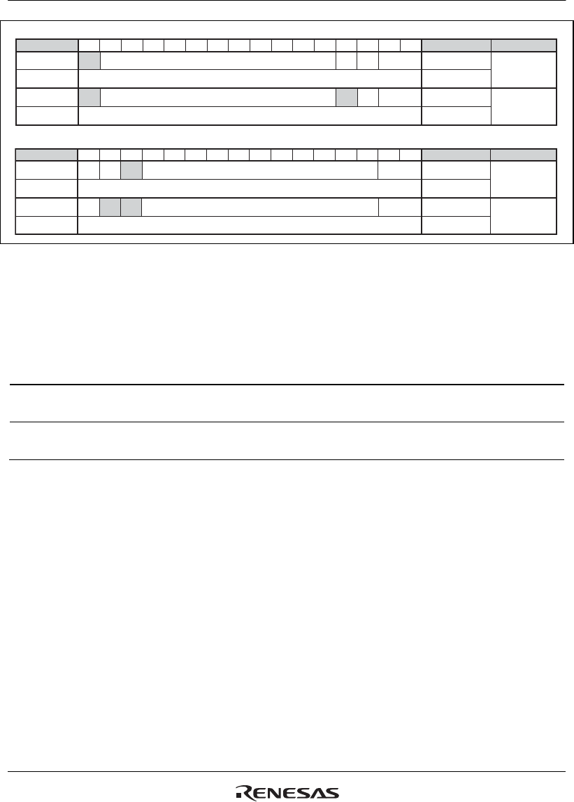
Figure 20.10 ID Reorder
This bit can be modified only in reset mode.
Bit 14 — Auto Halt Bus Off (MCR14): If both this bit and MCR6 are set, MCR1 is
automatically set as soon as this module enters BusOff.
Bit14: MCR14 Description
0 This module remains in BusOff for normal recovery sequence (128 x 11
Recessive Bits) (Initial value)
1 This module moves directly into Halt Mode after it enters BusOff if MCR6 is
set.
This bit can be modified only in reset mode.
Bit 13 — Reserved. The written value should always be ‘0’ and the returned value is '0'.
Bit 12 — Reserved. The written value should always be ‘0’ and the returned value is '0'.
Bit 11 — Reserved. The written value should always be ‘0’ and the returned value is '0'.
Bit 10 - 8 — Test Mode (TST[2:0]): This bit enables/disables the test modes. Please note that
before activating the Test Mode it is requested to move this module into Halt mode or Reset mode.
This is to avoid that the transition to Test Mode could affect a transmission/reception in progress.
For details, please refer to section 20.4.1, Test Mode Settings.
Please note that the test modes are allowed only for diagnosis and tests and not when this module
is used in normal operation.


