Section 21 IEBus
TM
Controller
Page 1104 of 2108 R01UH0134EJ0400 Rev. 4.00
Sep 24, 2014
SH7262 Group, SH7264 Group
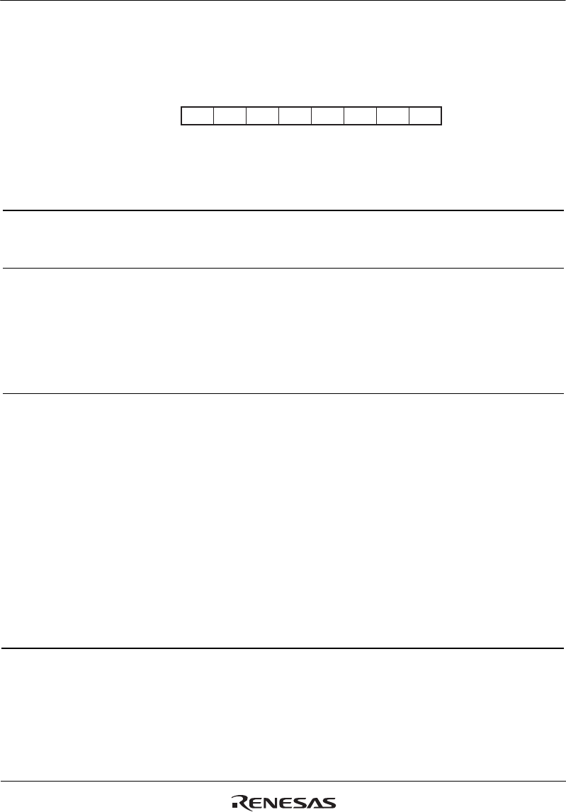
21.3.1 IEBus Control Register (IECTR)
IECTR is used to control the operation of this module.
76543210
00000000
R R/W R/W R R/W R R R
Bit:
Initial value:
R/W:
- IOL DEE - RE - - -
Bit Bit Name
Initial
Value
R/W Description
7 0 R Reserved
This bit is always read as 0. The write value should
always be 0.
6 IOL 0 R/W Input/Output Level
Selects input/output pin level (polarity) for the IERxD
and IETxD pins.
0: Pin input/output is set to active low. (Logic 1 is low
level and logic 0 is high level.)
1: Pin input/output is set to active high. (Logic 1 is high
level and logic 0 is low level.)
5 DEE 0 R/W Broadcast Receive Error Interrupt Enable
If this bit is set to 1, a reception error interrupt occurs
when the receive buffer is not in the receive enabled
state during broadcast reception (when the RE bit is not
set to 1 or the RXBSY flag is set.). At this time, the
master address is stored in IEBus reception master
address register 1 and 2.
While this bit is 0, a reception error interrupt does not
occur when the receive buffer is not in the receive
enabled state, and the reception stops and enters the
wait state. The master address is not saved.
0: A broadcast receive error is not generated up to the
control field.
1: A broadcast receive error is generated up to the
control field.


