Section 24 A/D Converter
R01UH0134EJ0400 Rev. 4.00 Page 1263 of 2108
Sep 24, 2014
SH7262 Group, SH7264 Group
24.3.1 A/D Data Registers A to H (ADDRA to ADDRH)
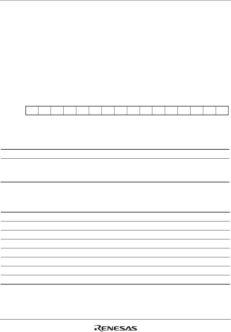
The sixteen A/D data registers, ADDRA to ADDRH, are 16-bit read-only registers that store the
results of A/D conversion.
An A/D conversion produces 10-bit data, which is transferred for storage into the ADDR
corresponding to the selected channel. The 10 bits of the result are stored in the upper bits (bits 15
to 6) of ADDR. Bits 5 to 0 of ADDR are reserved bits that are always read as 0.
Access to ADDR in 8-bit units is prohibited. ADDR must always be accessed in 16-bit units.
Table 24.3 indicates the pairings of analog input channels and ADDR.
15 14 13 12 11 10 9 8 7 6 5 4 3 2 1 0
0000000000000000
RRRR
Bit:
Initial value:
R/W:
------
RRRRRRRRRRRR
Bit Bit Name
Initial
Value R/W Description
15 to 6 All 0 R Bit data (10 bits)
5 to 0 All 0 R Reserved
These bits are always read as 0. The write value
should always be 0.
Table 24.3 Analog Input Channels and ADDR
Analog Input Channel A/D Data Register where Conversion Result is Stored
AN0* ADDRA
AN1* ADDRB
AN2* ADDRC
AN3* ADDRD
AN4 ADDRE
AN5 ADDRF
AN6 ADDRG
AN7 ADDRH
Note: * Only AN0 to AN3 can be used in the SH7262 Group.


