


Section 17 I
2
C Bus Interface 3
R01UH0134EJ0400 Rev. 4.00 Page 849 of 2108
Sep 24, 2014
SH7262 Group, SH7264 Group
Section 17 I
2
C Bus Interface 3
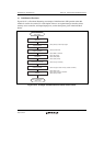
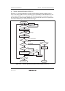
The I
2
C bus interface 3 conforms to and provides a subset of the Philips I
2
C (Inter-IC) bus
interface functions. However, the configuration of the registers that control the I
2
C bus differs
partly from the Philips register configuration.
The I
2
C bus interface 3 has three channels.
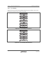
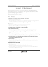
17.1 Features
Selection of I
2
C format or clocked synchronous serial format
Continuous transmission/reception
Since the shift register, transmit data register, and receive data register are independent from
each other, the continuous transmission/reception can be performed.
I
2
C bus format:
Start and stop conditions generated automatically in master mode
Selection of acknowledge output levels when receiving
Automatic loading of acknowledge bit when transmitting
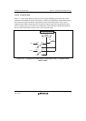
Bit synchronization function
In master mode, the state of SCL is monitored per bit, and the timing is synchronized
automatically. If transmission/reception is not yet possible, set the SCL to low until
preparations are completed.
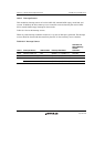
Six interrupt sources
Transmit data empty (including slave-address match), transmit end, receive data full (including
slave-address match), arbitration lost, NACK detection, and stop condition detection
The direct memory access controller can be activated by a transmit-data-empty request or
receive-data-full request to transfer data.
Direct bus drive
Two pins, SCL and SDA pins, function as NMOS open-drain outputs when the bus drive
function is selected.
Clocked synchronous serial format:
Four interrupt sources
Transmit-data-empty, transmit-end, receive-data-full, and overrun error
The direct memory access controller can be activated by a transmit-data-empty request or
receive-data-full request to transfer data.