


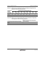

Section 28 Sampling Rate Converter
R01UH0134EJ0400 Rev. 4.00 Page 1651 of 2108
Sep 24, 2014
SH7262 Group, SH7264 Group
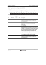
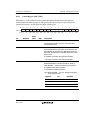
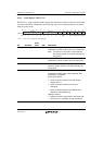
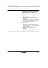
After flush processing has been completed, the number of output data units obtained as a result of
conversion can be calculated by using the following formula.
Number of output data units = Number of input data units ×
+ 1
6: When IFS[3:0] = 0000
4: When IFS[3:0] = (0001,0010)
3: When IFS[3:0] = (0100,1000)
2: When IFS[3:0] = (0101,0110)
1: When IFS[3:0] = (1001,1010)
n =
Output sampling rate
Input sampling rate
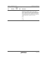
Channel 0
Input sampling rate
Channel 1
n = 1
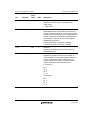
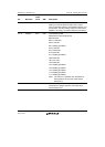
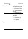
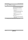
Conversion processing is not started and thus output data is not obtained until the specified
number of data units are input. The minimum number of input data units necessary for obtaining
the first output data depends on the IFS and OFS bit settings. Tables 28.7 to 28.10 show the
relation between the settings of the IFS and OFS bits and the number of input data required.
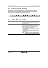
Table 28.7 Relation between Sampling Rate Settings and Number of Initial Input Data
Units Required (Channel 0)
OFS Setting
(Output
Sampling
Rate [kHz])
IFS Setting (Input Sampling Rate [kHz])
0000
(8.0)
0001
(11.025)
0010
(12.0)
0100
(16.0)
0101
(22.05)
0110
(24.0)
1000
(32.0)
1001
(44.1)
1010
(48.0)
0 (44.1) 38 40 40 43 48 48 43 63
1 (48.0) 38 40 40 43 48 48 43 32
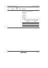
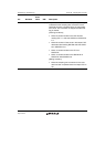
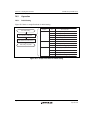
Table 28.8 Relation between Output Sampling Rate Settings and Number of Initial Input
Data Units Required (Channel 1)
OFS Setting (Output Sampling Rate [kHz]) Number of Initial Input Data Units
0 (8.0) 63
1 (16.0) 63