


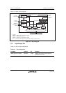

Section 13 Watchdog Timer
Page 670 of 2108 R01UH0134EJ0400 Rev. 4.00
Sep 24, 2014
SH7262 Group, SH7264 Group
13.4 Usage
13.4.1 Canceling Software Standby Mode
This module can be used to cancel software standby mode with an interrupt such as an NMI
interrupt. The procedure is described below. (This module does not operate when resets are used
for canceling, so keep the RES or MRES pin low until clock oscillation settles.)
1. Before making a transition to software standby mode, always clear the TME bit in WTCSR
to 0. When the TME bit is 1, an erroneous reset or interval timer interrupt may be generated
when the count overflows.
2. Set the type of count clock used in the CKS[2:0] bits in WTCSR and the initial value of the
counter in WTCNT. These values should ensure that the time till count overflow is longer than
the clock oscillation settling time.
3. After setting the STBY and DEEP bits of the standby control register 1 (STBCR1: see section
33, Power-Down Modes) to 1 and 0 respectively, the execution of a SLEEP instruction puts
the system in software standby mode and clock operation then stops.
4. This module starts counting by detecting the edge change of the NMI signal.
5. When the module count overflows, the clock pulse generator starts supplying the clock and
this LSI resumes operation. The WOVF flag in WRCSR is not set when this happens.
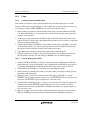
13.4.2 Using Watchdog Timer Mode
1. Set the WT/IT bit in WTCSR to 1, the type of count clock in the CKS[2:0] bits in WTCSR,
whether this LSI is to be reset internally or not in the RSTE bit in WRCSR, the reset type if it
is generated in the RSTS bit in WRCSR, and the initial value of the counter in WTCNT.
2. Set the TME bit in WTCSR to 1 to start the count in watchdog timer mode.
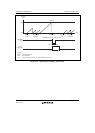
3. While operating in watchdog timer mode, rewrite the counter periodically to H'00 to prevent
the counter from overflowing.
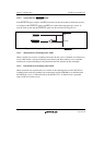
4. When the counter overflows, this module sets the WOVF flag in WRCSR to 1, and the
WDTOVF signal is output externally (figure 13.4). The WDTOVF signal can be used to reset
the system. The WDTOVF signal is output for 64 P clock cycles.
5. If the RSTE bit in WRCSR is set to 1, a signal to reset the inside of this LSI can be generated
simultaneously with the WDTOVF signal. Either power-on reset or manual reset can be
selected for this interrupt by the RSTS bit in WRCSR. The internal reset signal is output for
128 P clock cycles.
6. When an overflow reset of this module is generated simultaneously with a reset input on the
RES pin, the RES pin reset takes priority, and the WOVF bit in WRCSR is cleared to 0.