


Section 33 Power-Down Modes
Page 1776 of 2108 R01UH0134EJ0400 Rev. 4.00
Sep 24, 2014
SH7262 Group, SH7264 Group
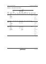
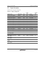
Bit Bit Name
Initial
Value R/W Description
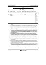
7 HIZ 0 R/W Port High Impedance
Selects whether the state of specific output pin is
retained or high impedance in software standby mode
or deep standby mode. As to which pins are
controlled, see appendix A, Pin States.
This bit must not be set while the TME bit in WTSCR
of the watchdog timer is 1. To set the output pin to
high-impedance, set the HIZ bit to 1 only while the
TME bit is 0.
0: The pin state is retained in software standby mode
or deep standby mode.
1: The pin is set to high-impedance in software
standby mode or deep standby mode.
6 MSTP36 1 R/W Module Stop 36
When the MSTP36 bit is set to 1, the clock supply to
the IEBus
TM
controller is halted.
0: The IEBus
TM
controller runs.
1: Clock supply to the IEBus
TM
controller is halted.
5 MSTP35 1 R/W Module Stop 35
When the MSTP35 bit is set to 1, the clock supply to
the multi-function timer pulse unit 2 is halted.
0: The multi-function timer pulse unit 2 runs.
1: Clock supply to the multi-function timer pulse unit 2
is halted.
4 MSTP34 1 R/W Module Stop 34
When the MSTP34 bit is set to 1, the clock supply to
the SD host interface 0 is halted.
0: The SD host interface 0 runs.
1: Clock supply to the SD host interface 0 is halted.
3 MSTP33 1 R/W Module Stop 33
When the MSTP33 bit is set to 1, the clock supply to
the SD host interface 1 is halted.
0: The SD host interface 1 runs.
1: Clock supply to the SD host interface 1 is halted.