Section 16 Renesas Serial Peripheral Interface
R01UH0134EJ0400 Rev. 4.00 Page 843 of 2108
Sep 24, 2014
SH7262 Group, SH7264 Group
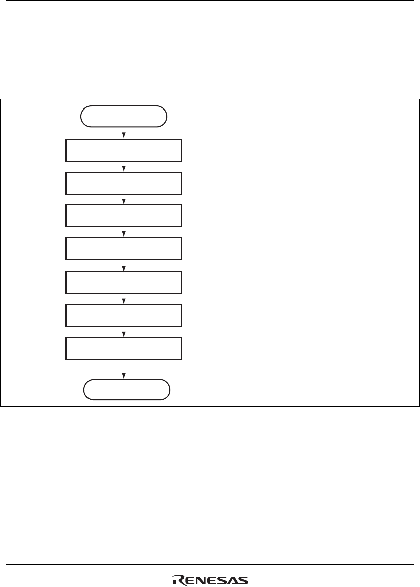
(e) Initialization Flowchart
Figure 16.19 is a flowchart illustrating an example of initialization in SPI operation when this
module is used in slave mode. For a description of how to set up the interrupt controller, direct
memory access controller, and input/output ports, see the descriptions given in the individual
blocks.
• Sets access width.
Set the pin control register
(SPPCR)
Set the slave select polarity
register (SSLP)
Set the data control
register (SPDCR)
Set the direct memory
access controller
Set the control register
(SPCR)
Set interrupt controller
Start of intialization in
slave mode
End of intialization in
slave mode
• Sets polarity of SSL input signal
• Sets clock polarity.
• Sets slave mode.
• Sets mode fault error detection.
• Sets interrupt mask.
(when using an interrupt)
(when using the direct memory access controller)
• Sets clock phase.
• Sets data length.
• Sets MSB or LSB first.
Set the command register 0
(SPCMD0)
Figure 16.19 Example of Initialization Flowchart in Slave Mode


