


Section 11 Multi-Function Timer Pulse Unit 2
R01UH0134EJ0400 Rev. 4.00 Page 555 of 2108
Sep 24, 2014
SH7262 Group, SH7264 Group
(j) Complementary PWM Mode PWM Output Generation Method
In complementary PWM mode, 3-phase output is performed of PWM waveforms with a non-
overlap time between the positive and negative phases. This non-overlap time is called the dead
time.
A PWM waveform is generated by output of the output level selected in the timer output control
register in the event of a compare-match between a counter and compare register. While TCNTS
is counting, compare register and temporary register values are simultaneously compared to create
consecutive PWM pulses from 0 to 100%. The relative timing of on and off compare-match
occurrence may vary, but the compare-match that turns off each phase takes precedence to secure
the dead time and ensure that the positive phase and negative phase on times do not overlap.
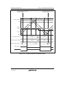
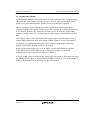
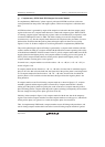
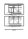
Figures 11.46 to 11.48 show examples of waveform generation in complementary PWM mode.
The positive phase/negative phase off timing is generated by a compare-match with the solid-line
counter, and the on timing by a compare-match with the dotted-line counter operating with a delay
of the dead time behind the solid-line counter. In the T1 period, compare-match a that turns off the
negative phase has the highest priority, and compare-matches occurring prior to a are ignored. In
the T2 period, compare-match c that turns off the positive phase has the highest priority, and
compare-matches occurring prior to c are ignored.
In normal cases, compare-matches occur in the order a b c d (or c d a' b'), as
shown in figure 11.46.
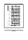
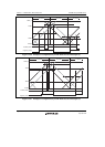
If compare-matches deviate from the a b c d order, since the time for which the negative
phase is off is less than twice the dead time, the figure shows the positive phase is not being turned
on. If compare-matches deviate from the c d a' b' order, since the time for which the
positive phase is off is less than twice the dead time, the figure shows the negative phase is not
being turned on.
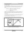
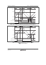
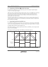
If compare-match c occurs first following compare-match a, as s
hown in figure 11.47, compare-
match b is
ignored, and the negative phase is turned off by compare-match d. This is because
turning off of the positive phase has priority due to the occurrence of compare-match c (positive
phase off timing) before compare-match b (positive phase on timing) (consequently, the waveform
does not change since the positive phase goes from off to off).
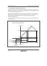
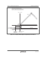
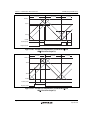
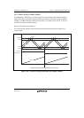
Similarly, in the example in figure 11.48, compare-match a' with the new data in the temporary
register occurs before compare-match c, but other compare-matches occurring up to c, which turns
off the positive phase, are ignored. As a result, the negative phase is not turned on.
Thus, in complementary PWM mode, compare-matches at turn-off timings take precedence, and
turn-on timing compare-matches that occur before a turn-off timing compare-match are ignored.