Teledyne API Model 200AU NO
X
Analyzer Instruction Manual, 02293, Rev. F
7-15
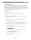
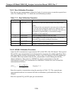
7.6.4.3 Example Calculation
Following is an example calculation that can be used to determine whether an existing GPT
calibrator will meet the required conditions for a specific calibration. For this example, it is
assumed that only the volume of the reaction chamber, V
RC
, and the concentration of the NO
standard, [NO]
STD
, are known. All flow settings (F
NO
, F
O
, F
T
, and F
D
) will be calculated. In many
uses, these flow settings are known and need only to be substituted in Equations 7-5 and 7-6 to
verify the required conditions. Before doing any calculations, the URL and flow demand of the
analyzer being calibrated must be known. For the M200AU:
Upper range limit = 0.5 ppm
Flow demand = 1000 cm
3
/min.
Volume of calibrator reaction chamber is determined by physical measurement:
V
RC
= 180 cm
3
The concentration of the NO standard gas to be used is determined by reference against an
NIST-SRM (Section 2.0.7, Q.A. Handbook):
[NO]
STD
= 50.5 ppm
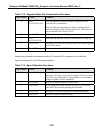
1. Determine the total flow (F
T
) required at the output manifold using Equation 7-1:
F
T
= 1000 cm
3
/min (110/100) = 1100 cm
3
/min
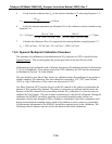
Because low flows are difficult to control and measure, it is often advantageous to set a
higher total flow than needed. In this example, we will let F
T
= 3300 cm3/min
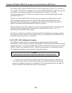
2. Determine the NO conc, [NO]
OUT
, required at the output manifold, using Equation 7-2:
[NO]
OUT
= 0.5 ppm (90/100) = 0.45 ppm
3. Calculate the NO flow (F
NO
) required to generate [NO]
OUT
, using Equation 7-3:
ppm5.50
min/
cm
3300ppm45.0
=
F
3
NO
=
×
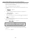
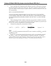
4. Calculate the required flow rate through ozone generator (F
O
) using Equation 7-4:
O
33
3
F
=
50.5 ppm x 2
cm
/ x 180
cm
2.75 ppm -
- 2
cm
/
94
94
. min
min
. min
=
cm
/ - 2
cm
/ = 2
cm
/
62 3 3
97180 9 4 82
min
. min min


