


Teledyne API Model 200AU NO
X
Analyzer Instruction Manual, 02293, Rev. F
8-16
3. Pressurize system and check for leaks by watching overall pressure. The pressure should
not drop more than 1"-Hg (0.5psi) in 5 minutes.
If the instrument fails the pressure test, each fitting needs to be leak checked to find the location.
Be careful that the system is always pressurized so as not to draw soap solution into the
plumbing system. Make sure you dry off any accumulated bubble solution. Refer to Figure 8-5,
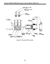
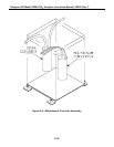
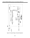
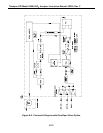
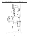
Figure 8-6 and Figure 8-7 for pneumatic diagrams.
The Sensor module can be leak checked as a unit using a 1/8" tubing fitting on top of the
assembly. The same rules as above apply.
1. Pressurize to <15psi.
2. After turning off pressure tester, pressure should not drop more than 1" Hg in 5 minutes.
8.8 Light Leak Check Procedure
1. Scroll the TEST functions to PMT.
2. Input zero gas
3. Shine a powerful flashlight or portable incandescent light at the inlet and outlet fitting,
and at all the joints of the reaction cell. The PMT value should not respond to the light.
If there is a response, tighten the joints or replace the tubing with new black PTFE tubing.
We often find light leaks are caused by o-rings being left out of the assembly.
8.9 Prom Replacement Procedure
Preparation: If any setup changes such as RANGE, AUTOCAL ON/OFF etc. have been made,
record the changes because all settings should be checked after the PROM is changed. See
Figure 9-2 for location of prom on CPU card.
1. Turn the machine off.
2. Remove the hold down screw that holds in the V/F-CPU assembly to the motherboard.
Disconnect the J9 power connector from the motherboard. Gently lift the assembly far
enough out of the instrument to remove the connector to the display and the RS-232
connector.
3. The CPU board is attached to the larger V/F board.