


Teledyne API Model 200AU NO
X
Analyzer Instruction Manual, 02293, Rev. F
9-60
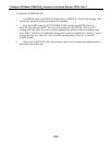
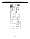
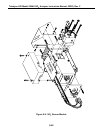
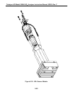
9.3.8 NO
x
Sensor Module
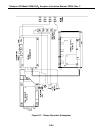
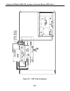
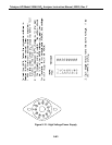
Figure 9-9 and Figure 9-10 show the assembly of the NO
x
sensor module.
9.3.8.1 PMT
The PMT detects the light emitted by the reaction of NO with ozone. It has a gain of about
500,000 to 1,000,000. It is not possible to test the detector outside of the instrument in the field.
The best way to determine if the PMT is working is by using Optic Test. OT operation is
described in Section 9.1.3.3.
The basic method to diagnose a PMT fault is to eliminate the other components using ET, OT
and specific tests for other sub-assemblies.
9.3.8.2 Reaction Cell Temp
The CPU controls the reaction cell temperature. It operates by reading a thermistor amplifier on
the Status/Temp board. The CPU controls the temperature by toggling a bit on the V/F board.
The V/F board TTL logic controls a solid state switch on the switch board in the PSM. The
switched 115VAC comes out of the PSM to a connector near the underside of the reaction cell.
A warning message may be present during initial warm-up or if the connector is not plugged in
after cleaning the reaction cell.
9.3.8.3 Preamp Board
The NO
x
Preamp Board is a multi-function board providing circuitry to support the following
functions.
1. Preamp, buffer amplifier, physical range control hardware for the PMT detector.
2. Precision voltage reference and voltage generation, and control for the PMT - HVPS
inside the sensor module.
3. Constant current generator and adjustment for the Optic Test LED.
4. Voltage generation and adjustment for Electric Test.
5. Thermistor amplifier, control signal generation for the PMT cooler.
The setup and adjustment of items 1-4 above is covered in the Factory Calibration procedure in
Section 9.1.6. Item 5 has no adjustable features.