


Teledyne API Model 200AU NO
X
Analyzer Instruction Manual, 02293, Rev. F
9-13
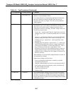
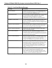
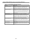
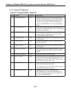
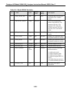
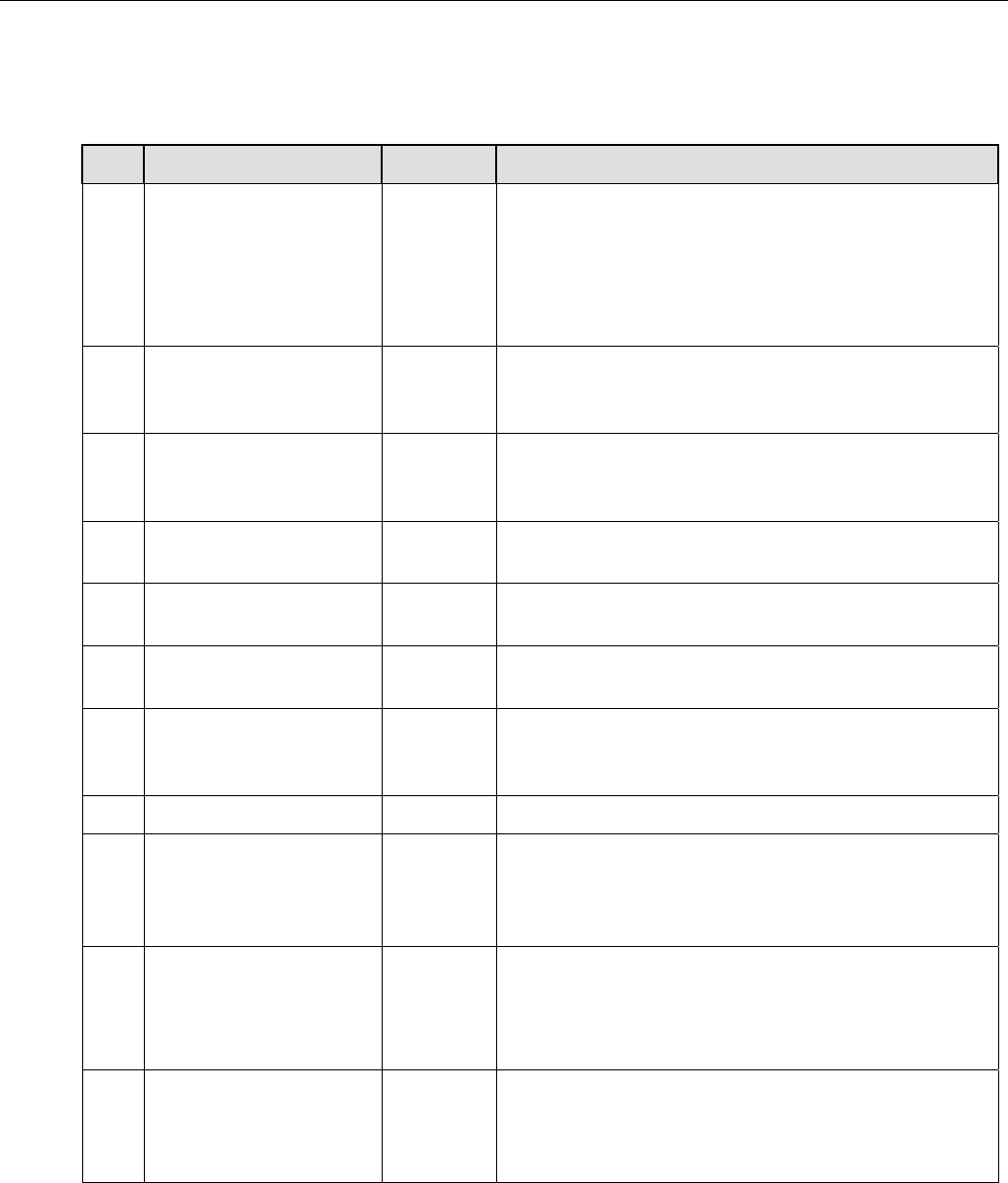
9.1.3.1 Signal I/O Diagnostic
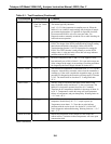
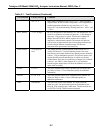
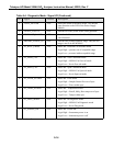
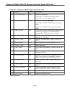
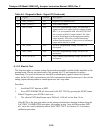
Table 9-4: Diagnostic Mode - Signal I/O
No. Signal Control Description
0 DSP_BROWNOUT NO Display brownout is used to keep the display from
getting corrupted during low line voltage conditions.
Circuitry on the Status/Temp board senses low line
voltage and sets this bit. The CPU reads this and
generates the BROWNOUT_RST signal described
below.
1 EXT_ZERO_CAL NO Shows state of status input bit to cause the M200AU
to enter Zero Calibration mode. Use to check external
contact closure circuitry.
2 EXT_SPAN_CAL NO Shows state of status input bit to cause the M200AU
to enter the Span Calibration mode. Use to check
external contact closure circuitry.
3 SPAN_VALVE YES Switches the Zero/Span valve. Use this bit to test the
valve function.
4 CAL_VALVE YES Switches the Sample/Cal valve. Use this bit to test
the valve function.
5 NOX_VALVE YES Switches the NO/NO
x
valve. Use this bit to test the
valve function.
6 RCELL_HEATER YES Shows the status of the reaction cell heater. This has
the same function as the LED in the Power Supply
Module.
7 BLOCK_HEATER YES Shows the status of the block heater.
8 ELEC_TEST YES Turns on electric test bit on the preamp board. Should
be used for troubleshooting Preamp logic lines. We
recommend you use the ELEC TEST button in the
DIAG menu to operate electric test.
9 OPTIC_TEST YES Turns on optic test bit in preamp. Should be used for
troubleshooting Preamp logic lines.
We recommend you use the OPTIC TEST button in
the DIAG menu to operate optic test.
10 BROWNOUT_RST YES Brownout reset works in conjunction with
DSP_BROWNOUT. When DSP_BROWNOUT is
set, the CPU sends a signal to reset the display and
clear the DSP_BROWNOUT.
(table continued)