


Teledyne API Model 200AU NO
X
Analyzer Instruction Manual, 02293, Rev. F
9-43
1. After the switches and jumpers are set, turn on instrument power and complete the
following:
A. Press SETUP-MORE-DIAG, then press ENTR. Scroll to D/A CALIBRATION, press
ENTR.
Press ADC to select the first task, which is to calibrate the A/D converter.
B. Connect a DVM ground lead to TP3-AGND on the V/F board. Connect the positive lead
to TP9-DAC0.
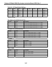
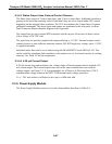
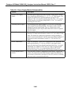
C. The M200AU will display a voltage near 1% of the voltage range set in the above
procedure. See Figure 9-4 for a table of approximate expected voltages. Adjust R27 until
the displayed voltage matches the DVM voltage, then press ENTR.
D. The M200AU will display a voltage near 90% of the voltage range set in the above
procedure. Adjust R31 until the displayed voltage matches the DVM voltage, then press
ENTR. This step calibrates the instrument A/D converter to the external DVM.
E. The M200AU will automatically scroll through the DAC output channels, calibrating
each one. The display will update the progress of the calibration. If operating all analog
outputs in voltage mode this completes the calibration procedure.
The calibration of each channel can be checked or recalibrated independently by scrolling the
PREV-NEXT buttons and pressing CAL for the desired channel. Also, a DC offset bias can be
entered by pressing the OFFSET button for the appropriate channel.
Calibrating a channel for current loop operation:
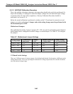
1. BEFORE STARTING, make sure that hardware settings are correct as shown in Table 9-
6 and Table 9-7.
2. Calibrate the A/D converter as described in item 2 above, if necessary.
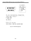
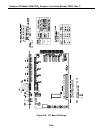
3. Connect a 250 ohm resistor in series with a current meter to the correct pair of terminals
on the rear panel, see Figure 2-2 for terminal assignments.
4. In the D/A calibration Menu press CFG, then use PREV-NEXT to select the channel to
be calibrated.
5. Press the SET button to select CURR for current loop operation, then press ENTR.
6. To enter the calibration routine press CAL.
7. To calibrate the 4 mA zero point, press the UP-UP10 - DN-DN10, then press ENTR.
8. The M200AU will then output 20 mA. Press the UP-UP10 - DN-DN10 buttons to
calibrate the span point, then press ENTR.
9. Repeat steps 2-6 for each channel that needs to be calibrated.