Teledyne API Model 200AU NO
X
Analyzer Instruction Manual, 02293, Rev. F
5-23
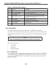
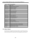
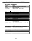
Table 5-8: M200AU Operating Modes
Mode Description
ZERO CAL D Automatic dynamic zero calibration
ZERO CAL A Automatic zero calibration
ZERO CAL R Remote zero calibration
ZERO CAL M Manual zero calibration
SPAN CAL D Automatic dynamic span calibration
SPAN CAL A Automatic span calibration
SPAN CAL R Remote span calibration
SPAN CAL M Manual span calibration
M-P CAL Manual multi-point calibration
DIAG ELEC Electrical diagnostic test
DIAG OPTIC Optical diagnostic test
DIAG OZONE Ozone generator diagnostic test
DIAG AOUT D/A output diagnostic test
DIAG Main diagnostic menu
DIAG I/O Signal I/O diagnostic
DIAG RS232 RS232 output diagnostic
SETUP x.x Setup mode (x.x is software version)
SAMPLE ZS Sampling; automatic dynamic zero and span calibration enabled
SAMPLE Z Sampling; automatic dynamic zero calibration enabled
SAMPLE S Sampling; automatic dynamic span calibration enabled
SAMPLE A Sampling; automatic cal. enabled
SAMPLE Sampling; automatic cal. disabled
5.4 Status Output
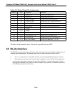
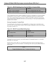
The status output is an option that reports Analyzer conditions via contact closures on the rear
panel. The closures are available on a 50 pin connector on the rear panel. The contacts are NPN
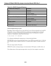
transistors which can pass 50 ma of direct current. The pin assignments are listed in Table 5-9.


