


Teledyne API Model 200AU NO
X
Analyzer Instruction Manual, 02293, Rev. F
9-6
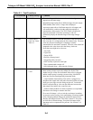
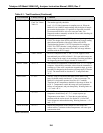
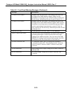
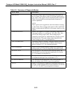
Table 9-1: Test Functions (Continued)
Test Function Factory Set-Up Comment
PREREACT Check value in
Final Test Values
Table 2-1
PREREACT is the current value of the Pre-reactor circuit reading.
The number typically should be
0 mV -15/+35 if the instrument is sampling zero air. When the
M200AU is in SAMPLE mode readings may be higher if sample
gas contains hydrocarbons. If a problem is suspected, check the
Pre-reactor and NO/NO
x
valves for cross port leaks. Use
Diagnostic mode to manually switch the valves while checking for
leaks and correct operation.
HVPS 450 – 900 VDC This represents the scaled-up HVPS programming voltage to the
HVPS. The design of the HVPS precludes taking a single reading
that indicates the health of the supply. Refer to the HVPS
Troubleshooting Section 9.3.8.5 for a procedure for testing the
HVPS. This TEST function is used primarily to set the HVPS
voltage value. A value not in the 450 to 900 volt range indicates
problems with the HVPS supply.
DCPS
2500
±
200 mV DCPS is a composite of the +5 and
±
15 VDC supplies. It has
been arbitrarily set at 2500
±
200 mV. If it is not in this range one
of the voltages in the supply is not working. Check the procedures
for diagnosing the Power Supply Module in Section 9.3.5.
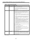
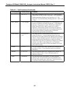
RCELL TEMP
40
±
1° C The reaction cell temperature is controlled to 40° C
±
1° C by the
computer. It should only read other values when the instrument is
warming up. If the value is outside the acceptable range, go to the
procedure for diagnosing the Reaction cell temp supply in Section
9.3.8.2. The alarm limits are less than 35° C and greater than
45° C.
BOX TEMP
8 - 48° C
The Box Temp is read from a thermistor on the Status/Temp
board. It should usually read about 5° C above room temp. The
M200AU is designed to operate from 20 to 30° C ambient.
Therefore the box temperature should be in the range of about 10
to 50° C. Temperatures outside this range will cause premature
failures of components, and poor data quality. Warning limits are
< 8° C and > 48° C.
PMT TEMP
-5
±
1° C
The PMT detector is very temperature sensitive. The PMT
temperature should always be –5° C, except at power-up.
Temperatures more than
±
1° C from the set point indicate
problems with the cooler circuit. See Section 9.3.8.4 for PMT
cooler diagnostic and troubleshooting. Warning limits are < -8° C
and > -2° C.
BLOCK TEMP
40 ± 2
o
C
Reports the temperature of the sample flow and ozone flow
control orifices. Variations in these temperatures will cause span
concentration drift.
(table continued)