


Teledyne API Model 200AU NO
X
Analyzer Instruction Manual, 02293, Rev. F
9-62
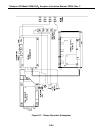
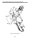
9.3.8.4 PMT Cooler
The PMT cooler uses a Peltier cooler supplied with DC current from the switching power supply
in the Power Supply Module. An overall view is shown in Figure 9-9. A proportional
temperature controller located on the Preamp board controls the temperature. Voltages applied to
the cooler element vary from .1 to 12 VDC. The input voltage from the supply is 15 VDC. The
actual -5
°
C setpoint will vary
±
1
°
C due to component tolerances. The temperature will be
maintained within 0.1
°
C about the setpoint. If the temperature fails to drop after a few minutes,
there is a problem in the cooler circuit. If the control circuit on the Preamp card is faulty a
temperature of -10
°
C is reported.
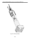
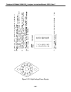
9.3.8.5 High Voltage P.S.
The HVPS is located in the interior of the Sensor Module, and is plugged into the PMT tube. It
requires 2 voltage inputs. The first is +15 VDC, which powers the supply. The second is the
programming voltage, which is generated on the Preamp Board. This power supply is unlike a
traditional PMT HVPS. It is like having 10 independent power supplies, one to each pin of the
PMT. The test procedure below allows you to test each supply.
Adjustment of the HVPS is covered in the Factory Calibration Procedure in Section 9.1.6. To
troubleshoot the HVPS:
1. Turn off the instrument.
2. Remove the cover and disconnect the 2 connectors at the front of the NO
x
Sensor
Module.
3. Remove the end cap from the sensor.
4. Remove the HVPS/PMT assembly from the cold block inside the sensor. Un-plug the
PMT tube.
5. Re-connect the 7 pin connector to the Sensor end cap, and power-up the instrument.
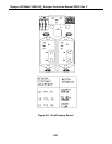
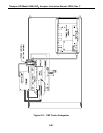
6. Use Figure 9-12 to check the voltages at each pin of the supply, and the overall voltage.
7. Turn off the instrument power, and re-connect the PMT tube, then re-assemble the
sensor.
If any faults are found in the test, you must obtain a new HVPS as there are no user serviceable
parts inside the supply.