


Teledyne API Model 200AU NO
X
Analyzer Instruction Manual, 02293, Rev. F
7-13
Given that the NO concentration is known for this reaction, the resultant concentration of NO
2
can be determined. Ozone is added to excess NO in a dynamic calibration system, and the NO
channel of the chemiluminescent analyzer detects the changes in NO concentration. After the
addition of O
3
, the observed decrease in NO concentration on the calibrated NO channel is
equivalent to the concentration of NO
2
produced. The amount of NO
2
generated may be varied
by adding varying amounts of O
3
from a stable O
3
generator. All zero air used in this procedure
should conform to the requirements stated in Section 7.
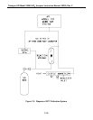
Dynamic calibration systems based on this principle are commercially available such as the
Teledyne API Model 700 Calibrator, or may be assembled by the user. A recommended
calibration system is described in the Federal Register
1
and detailed in TAD.
2
7.6.4.2 GPT Calibrator Check Procedure
It has been determined empirically that the NO-O
3
reaction goes to completion (<1% residual
O
3
) if the NO concentration in the reaction chamber (ppm) multiplied by the residence time
(min.) of the reactants in the chamber is >2.75 ppm-min. The theory behind the development of
this equation is in the Federal Register
1
and in TAD.
2
It is currently not known whether this relationship holds up at the extremely low concentrations
of which the M200AU is capable. We therefore recommend that the GPT procedure be carried
out at the normal flow-rate and concentrations encountered in ambient air monitoring, then
performing a serial dilution of the resultant gas stream to get the low concentration values.
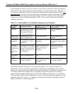
The following procedures and equations should be used to determine whether an existing GPT
calibration system will meet required conditions for a specific calibration.
For calibrators that have known pre-set flow rates, use equations 7-5 and 7-6 of steps 7 and 8
(below) to verify the required conditions. If the calibrator does not meet specifications, follow
the complete procedure to determine what flow modifications must be made.
1. Select a NO standard gas that has a nominal concentration in the range of 50 to 100 ppm.
Determine the exact concentration [NO]
STD
by referencing against an NIST-SRM, as
discussed in Section 2.0.7 (Q.A. Handbook).
2. Determine the volume (cm
3
) of the calibrator reaction chamber (V
RC
). If the actual
volume is not known, estimate the volume by measuring the approximate dimensions of the
chamber and using an appropriate formula.
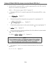
3. Determine the required minimum total flow output (F
T
) using Equation 7-1:
F
T
= analyzer flow demand (cm
3
/min) x 110/100 Equation 7-1
If more than one analyzer is to be calibrated at the same time, multiply F
T
by the number of
analyzers.