Teledyne API Model 200AU NO
X
Analyzer Instruction Manual, 02293, Rev. F
9-22
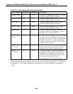
Table 9-6: Test Channel Readings (Continued)
TEST Channel Minimum* Maximum* Description
RCELL TEMP 0
o
C 70
o
C Reaction Cell temperature is set to 50
o
C. At the
setpoint, a typical reading is 3600 mV.
BLOCK TEMP 0
o
C 70
o
C The Block temperature is set to 50
o
C. At the
setpoint, a typical reading is 3600 mV.
IZS TEMP 0
o
C 70
o
C The IZS temperature is set to 50
o
C. At the
setpoint, a typical reading is 3600 mV.
CONV TEMP 0
o
C 1000
o
C The Converter temperature is 315
o
C. At the
setpoint, a typical voltage is 3150 mV.
PMT TEMP 0
o
C 70
o
C The PMT temperature is unique in that the
voltage is inverse to the temperature. A typical
reading for 8
o
C would be 4200 mV.
CHASSIS
TEMP
0
o
C 70
o
C The Chassis (Box) temperature is variable due to
variable ambient air temperature. The Box temp
generally runs about 5
o
C above the surrounding
air temp. Thus in a 25
o
C room, the Box temp
would be about 30
o
C and have a TEST channel
voltage of about 2000 mV.
DCPS
VOLTAGE
0 mV 5000 mV The DCPS is a composite of several DC power
supply voltages in the instrument. It has been
arbitrarily set at 2500 mV, which is typical.
HVPS
VOLTAGE
0 V 5000 V The HVPS voltage is a scaled up reading of the
programming voltage going to the HVPS. Zero
to 1000 mV corresponds 0-1000 VDC for the
HVPS, which is the maximum voltage possible.
A typical reading would be 700 mV
corresponding to 700 VDC for the HVPS.
* Minimum and Maximum readings depend on the DAC 3 switch settings of the V/F board. For
the standard
±
5 VDC range, minimum corresponds to 0 VDC and maximum corresponds to
5 VDC.


