


Teledyne API Model 200AU NO
X
Analyzer Instruction Manual, 02293, Rev. F
2-1
2 GETTING STARTED
2.1 Unpacking
1. Verify that there is no apparent shipping damage. If damage has occurred please advise
shipper first, then Teledyne API.
CAUTION
To avoid personal injury, always use two persons to
lift and carry the Model 200AU.
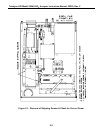
2. Before operation, it is necessary to remove the shipping hold-down screws. Remove the
instrument cover, then refer to Figure 2-1 for screw location.
3. Also check for internal shipping damage, and generally inspect the interior of the
instrument to make sure all circuit boards and other components are in good shape.
4. Please check the voltage and frequency label on the rear panel of the instrument for
compatibility with the local power before plugging in the M200AU.
2.2 Electrical and Pneumatic Connections
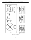
Refer to Figure 2-2 to locate the rear panel electrical and pneumatic connections.
1. Attach the pump to the Exhaust Out port on the instrument rear panel.
2. If you are connecting to a calibrator, attach a vented sample inlet line to the sample inlet
port. The pressure of the sample gas at the inlet port should be at ambient pressure. The
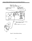
exhaust from the pump should be vented to atmospheric pressure. See Figure 2-3 for inlet
and exhaust line venting recommendations during calibration.
3. If desired, attach the analog output connections to a strip chart recorder and/or
datalogger. Refer to Figure 9-4 for the jumper settings for the desired analog output voltage
range. Factory default setting is 0-5VDC.
4. Connect the power cord to the correct voltage line, then turn to Section 2.3 Initial
Operation.