


Teledyne API Model 200AU NO
X
Analyzer Instruction Manual, 02293, Rev. F
4-5
4.2.5 Front Panel
The front panel of the M200AU is shown in Figure 2-4. The front panel consists of a 2 line
display and keyboard, 3 status LED's and power switch. Communication with the display,
keyboard, and status LED's is done via the computer's on-board parallel port. The M200AU was
designed as a computer controlled instrument, therefore all major operations can be controlled
from the front panel display and keyboard.
The display consists of 2 lines of 40 characters each. The top line is divided into 3 fields, and
displays information. The first field is the mode field. A list of operating modes is given in
Table 5-8.
The center field displays TEST values. The TEST functions allow you to quickly access many
important internal operating parameters of the M200AU. This provides a quick check on the
internal health of the instrument. The right hand field shows current concentration values of NO,
NO
x
, and NO
2
. The display scrolls between the 3 values every 4 seconds.
4.2.5.1 Keyboard
The second line of the display contains eight fields. Each field defines the key immediately
below it. By redefining the keys dynamically it is possible to simplify the instrument electronics
and user interface.
When entering data in the keyboard, if the entered value is not accepted, the M200AU will
"beep" to notify the user that the value keyed in was not accepted. The original value remains
unchanged.
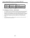
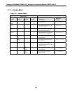
4.2.5.2 Status LED's
At the right of the display there are 3 status LED's. They can be in three states, OFF, ON, and
Blinking. The meanings of the LED's are given in Table 4-1.