


Teledyne API Model 200AU NO
X
Analyzer Instruction Manual, 02293, Rev. F
9-45
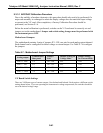
9.3.3.2 Changing Output Voltage Ranges
Several different output voltage ranges can be selected by switches on the V/F board. See Figure
9-4 for the switch settings.
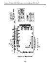
9.3.4 Status/Temp Board
The Status/Temp Board is a multi-function board that:
1. Converts the resistance readings of the thermistors to voltages
2. Conditions the thermocouple voltage for the V/F card
3. Provides status output circuitry
4. Provides circuitry for contact closure inputs
5. Provides circuitry for display brown-out/reset at low line voltage
6. Provides chip carriers for voltage-to-current modules
9.3.4.1 Temperature Amplifier Section
The Status/Temp board is a multi-function board consisting of 4 thermistor amplifiers that
monitor:
1. IZS temperature (not available on the M200AU)
2. Reaction Cell temperature
3. Box temperature
4. Spare
All 4 amplifiers have a single gain control - R34. If necessary, you can adjust the temperature
values by selecting the BOX TEMP - TEST function and adjusting R34 until the correct box
temp is shown. Remember that the temperature inside the case runs several degrees higher than
room temperature, which should be taken into account when setting BOX TEMP.
The voltages of the thermistor and thermocouple amplifier outputs are brought out to test points
on the edge of the board. Refer to the Status/Temp board schematic for details. The voltages can
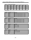
also be read using the DIAGNOSTIC - SIGNAL I/O feature. See Table 9-4 for details.