


Teledyne API Model 200AU NO
X
Analyzer Instruction Manual, 02293, Rev. F
4-4
NOTE
On vacuum vs absolute pressure:
Many vacuum gauges read relative to ambient pressure, therefore
a reading of 25" of mercury (Hg) at sea level (which would give an
absolute pressure of about 5" Hg in the reaction cell) would read
only 20" Hg at high altitude sites. Therefore in this manual the vacuum
specification of 5" Hg pressure is given as an absolute pressure
- 5"Hg-A - reference against zero absolute pressure (a perfect vacuum)
thus removing ambiguities for high altitude sites.
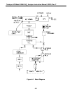
4.2.3 Computer Hardware and Software
CPU Board
The M200AU Analyzer is operated by an V40 series micro computer. The computer's
multitasking operating system allows it to do instrument control, monitor test points, provide
analog output and provide a user interface via the display, keyboard and RS-232 port. These
operations appear to be happening simultaneously but are actually done sequentially based on a
priority queuing system maintained by the operating system. The jobs are queued for execution
only when needed, therefore the system is very efficient with computer resources.
The M200AU is a true computer based instrument. The microprocessor does most of the
instrument control functions such as temperature control, valve switching. Data collection and
processing are done entirely in the CPU with the final concentration values being sent to a D/A
converter to produce the instrument analog output.
The computer memory is divided into 3 sections: ROM memory contains the multi-tasking
operating system code plus the instructions that run the instrument. The RAM memory is used to
hold temporary variables, current concentration data and data acquisition system data. The
EEPROM memory contains the instrument set-up variables such as range and instrument ID
number. The EEPROM data is non-volatile so the instrument can lose power and the current set-
up information is preserved.
4.2.4 V/F Board
The V/F board is multifunctional, consisting of A/D input channels, digital I/O channels, and
analog output channels. Communication with the computer is via a STD bus interface. The
computer receives all of the instrument data and provides all control functions through the V/F
board.