


Teledyne API Model 200AU NO
X
Analyzer Instruction Manual, 02293, Rev. F
9-40
4. Use a DVM on each of the analog output channels to confirm the correct voltages.
If the voltages step, but are the wrong values, the V/F board may be set up wrong or out of
calibration. See Section 9.3.3.1 for information on how to calibrate the V/F board.
5. Digital input channel test.
The digital I/O section of the V/F board has 8 input bits and 24 output bits. Two of the 8
input bits are assigned as calibration controls. See Section 7.5 for information on calibration
using external contact closures.
To test the digital inputs:
A. Turn on the M200AU.
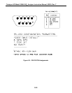
B. Connect a jumper wire across pins 1 and 2 of the rear panel connector as shown in
Figure 2-2.
C. Shortly after closure is made the instrument should switch into zero mode as indicated on
the front panel display.
D. Remove the jumper.
6. Digital output channel test.
There are 24 output bits on the V/F board. The 24 bits are made up of 3 - 8 bit ports. It is
possible for a single 8 bit port or even a single bit within a port to fail.
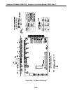
A quick observational test of the digital outputs is to observe the LED's in the Power Supply
Module(Refer to Figure 9-5 for the location of the LED's in the PSM) The state of the LED's
can be checked from Table 4-1. The comments section assumes the M200AU has been
running for at least 45 minutes.
A more detailed test is in the DIAGNOSTIC menu. See Diagnostic tests in Section 9.1.3.