


Teledyne API Model 200AU NO
X
Analyzer Instruction Manual, 02293, Rev. F
9-48
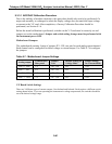
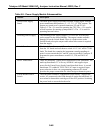
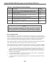
Table 9-9: Power Supply Module Subassemblies
Module Description
Linear Power Supply
Board
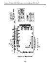
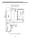
The linear power supply board takes multiple voltage inputs from the
power transformer and produces +5, +15, -15, +12 VDC outputs. The
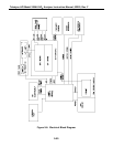
outputs are routed to two external connectors, P2 and P3. See
Figure 9-5. The +5 is used for operating the CPU. The ± 15 is used in
several locations for running op-amps and IC's. The +12 is used for
operating fans and valves.
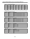
Switching Power Supply The switching power supply supplies +15 VDC at 4 A to the PMT
cooler control on the Sensor Module. The output is made available
through J10 on the Switch Board. There is a load resistor on the
Switch Board to keep the output stable when little current is required
from the supply.
Switch Board The Switch Board has many different functions. It takes logic signals
from the V/F board and uses them to switch 4-115 VAC and 4-12VDC
loads. The board also contains the instrument central grounding tie
point. It routes unswitched AC and DC power as needed. Connector J2
programs the power transformers to take 115, 220, and 240 VAC
inputs
Power Transformers There are potentially 2 input power transformers in the instrument. The
multi-tap transformer T1 is in every M200AU and supplies input
power for the Linear Power Supply board described above. A second
transformer T2 is added if 220 or 240 VAC input is required. Input
power selection is done via a programming connector P2 which
provides the proper connections for either foreign or domestic power.
Circuit Breaker/Power
Switch
The front panel contains a combination circuit breaker - input power
switch. It is connected to the PSM through J6 on the Switch Board. If
an overload is detected the switch goes to the OFF position. Switching
the power back on resets the breaker also.