


PathBuilder S24x, 26x, and 27x Switch Hardware Installation 3-9
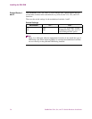
DSU Input and Output Signaling
You can view these signals using the control terminal Monitor menu item on the
Main menu.
Other Reporting
Differences
Other differences in control terminal output are:
• Detailed Port Statistics— show DSU input and output signaling as well as
note the installed DSU DIM
• Detailed Node Statistics— show DSU DIM position
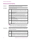
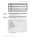
Example of
Diagnostics Menu
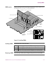
Figure 3-3 shows the Diagnostics menu. Use this menu to access the loopback
options described in the next section.
Figure 3-3. Diagnostics Menu
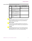
CL CSU Loopback
When this signal is “L”, the DSU hardware is looping the remote
connection's receive to transmit.
IDL Idle
An “H” on this signal tells the DSU hardware to send idle bipolar
violations to the remote system.
CLK Clock Mode
The signal “H” denotes the use of the network clock. The DSU option
provides the clock when this signal is “L”.
Signal Description (continued)
Node: nodename Address (blank)Date: ___________Time:__________
Menu: Diagnostics Path: (Main.12)
1. Local Loopback
2. V.54 Loopback 2
3. V.54 Loopback 3
4. Fatal Error Reports
5. Logged Alarms«
6. Startup Diagnostics
7. DSU Internal Loopback
8. DSU Internal and External Loopback
9. Start Delay Measurement
10. Stop Delay Measurement
11. Display Delay Summary
12. IP Ping
#Enter Selection: