


1-26 About the PathBuilder S24x, 26x, and 27x switch
Hardware Components
DSPM Card with Analog E&M Interface
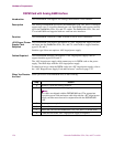
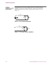
Introduction The DSPM/E&M card supports two analog E&M interface voice channels.
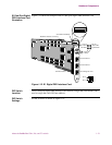
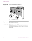
Description The Analog DSPM/E&M card allows the PathBuilder S24x, 26x, and 27x switch to
support up to two (2) voice/fax channels per card. Each E&M card occupies one ISA
slot in the PathBuilder S24x, 26x, and 27x switch. The PathBuilder S24x, 26x, and
27x switch E&M card supports both two- and four-wire interfaces.
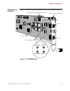
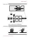
Function The DSPM/E&M card allows a PBX to attach to one of its two connectors.
-48V Ringer/ Power
Supply Card
Required
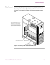
The DSPM/E&M card requires installation of a -48V ringer/power supply card and
enclosure into the PathBuilder S24x, 26x, and 27x switch node to support interface
types II, III, and V.
Interface type I does not require a -48V ringer/power supply.
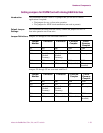
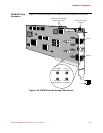
Cables Required The DSPM/E&M interface card requires a -48V ringer/power supply cable to
support interface types II, III, and V.
The -48V ringer/power supply cable connects up to six DSPM cards to the power
supply. The cable ships with the -48V ringer/power supply.
For details on how to cable the DSPM card to the -48V ringer/power supply, refer to
the “-48V Ringer/Power Supply Card and Enclosure” section on page 1-53.
When You Receive
the Card
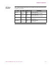
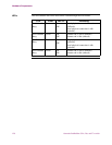
When you receive a DSPM/E&M card, do the following:
Step Action
1 Remove it from the packing material.
2 Inventory the contents of the shipping container.
N
o
t
e
No cables are shipped with the DSPM/E&M card. The appropriate
6-position power cable and status cable ship with the -48V ringer/power
supply card that must be used in conjunction with the DSPM/E&M
card.
3 Set jumpers as required.
4 Power off the node.
5 Install the card into the PathBuilder S24x, 26x, and 27x switch node.
6 Cable the card to the -48V ringer/power supply as required.