


Channelized Data 5-21
Configuring Channelized Data
Configuring the
Virtual Mapping
Table
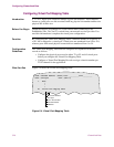
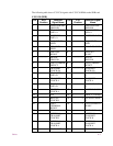
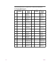
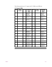
Perform this procedure to configure the Virtual Port Mapping Table.
Virtual Port
Mapping Table
Parameters
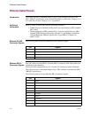
This section describes parameters for the Virtual Port Mapping Table.
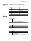
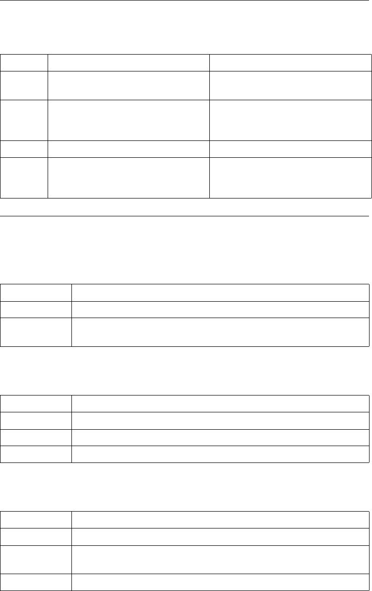
Step Action Result
1 From the CTP Main menu, select
Configure.
The Configure menu appears.
2 Select Virtual Port Mapping
Table from the Configure menu.
The first parameter appears—
Virtual Port Number—as shown
in Figure 5-4.
3 Enter a value for each parameter. The next parameter appears.
4 Enter a semicolon <;> once you
have entered values for all
parameters.
The record is saved.
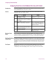
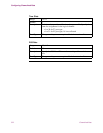
Virtual Port Number
Range: 100 to 254
Default: (blank)
Description: The timeslot logical channel (a virtual port number) to which a
specific T1 or E1 card’s port number is mapped.
Port Type
Range: Voice, Data
Default: Voice
Description: Specify the type of traffic you are passing.
Boot Type: Changes to this parameter require a Node boot to take effect.
Physical T1/E1 Port Number
Range: 49 or 50
Default: (blank)
Description: T1 or E1 port number associated with this logical timeslot channel
(a virtual port number).
Boot: Changes to this parameter require a Node boot to take effect.