


About the PathBuilder S24x, 26x, and 27x switch 1-11
Hardware Components
Enclosure
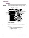
Introduction This section provides detailed information about the parts of the PathBuilder S24x,
26x, and 27x switch enclosure.
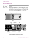
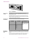
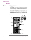
Front Panel The PathBuilder S24x, 26x, and 27x switch front panel (see Figure 1-6) has:
• Three status LEDs
• A 2-character numeric LED display
• A RESET switch
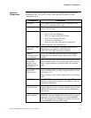
Status LEDs The three status LEDs are:
• Power (green) — When on, indicates that power is on and all DC voltages are
within specifications.
• Status (green) — When on, indicates that the PathBuilder S24x, 26x, and 27x
switch node is executing either a power-up diagnostic or a software download.
This LED is normally off.
• Service (yellow) — When on, indicates a hardware failure. This LED is
normally off.
Numeric LED
Display
The 2-character numeric LED display provides system diagnostic codes. When the
Service LED is on, a 2-digit code on the numeric LED display corresponds to a
certain event.
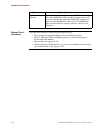
Reset Switch The RESET switch resets the node. Pressing the RESET switch is the equivalent of a
power-up operation which clears all existing calls and brings down all links.
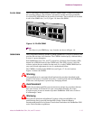
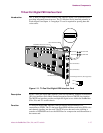
Power Supply The power supply is mounted at the top rear of the chassis. The AC switchable power
supply can operate at a nominal 110 or a nominal 230 Volts. For information about
maintaining and replacing the power supply, refer to Chapter 4, Maintenance.
Note
For this unit, the -48VDC Power Option is also available.