Cables A-1
Appendix A
Cables
Overview
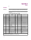
Introduction The tables in this appendix describe the pinouts for ports on the PathBuilder S24x,
26x, and 27x switch. Cable pinouts for Ethernet and LAN cables are also provided.
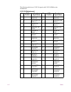
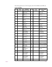
The following table shows EIA 232-D signals with V.24 DIMs on the motherboard
and SDB cards.
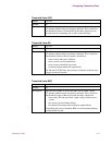
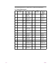
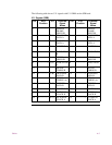
EIA 232-D Signals (Motherboard and SDB)
Pin DCE
Position
Function/Signal
Name
Pin DTE
Position
Function/Signal Name
1 --------------- Shield/Frame Ground 1 --------------- Shield/Frame Ground
2 <------------- TXD 2 --------------> TXD
3 --------------> RXD 3 <------------- RXD
4 <------------- RTS 4 -------------> RTS
5 --------------> CTS 5 <------------- CTS
6 --------------> DSR 6 <------------- DSR
7 --------------- Signal Ground 7 --------------- Signal Ground
8 --------------> DCD 8 <------------- DCD
14 <------------- DATA RESTRAINT 14 --------------> DATA RESTRAINT
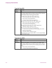
15 --------------> TRANSMIT CLOCK or
V.54 Loop 3 *
15 <------------- TRANSMIT CLOCK
16 --------------> STANDBY
INDICATOR
16 <------------- STANDBY INDICATOR
17 --------------> RECEIVE CLOCK 17 <------------- RECEIVE CLOCK
18 <-------------- EXTERNAL RECEIVE
CLOCK
18 --------------> EXTERNAL RECEIVE
CLOCK or V.54 Loop 3 *
20 <------------- DTR 20 --------------> DTR
21 <------------- V.54 Loop 2 21 --------------> V.54 Loop 2
22 <------------> RI/TM * 22 <------------ RI
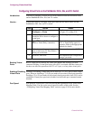
24 <------------- EXTERNAL
TRANSMIT CLOCK
24 --------------> EXTERNAL TRANSMIT
CLOCK
25 <---------- MAKE BUSY 25 -------------> TEST MODE
* Pin assigned double function as follows:
Outputs RI when switch is on. Otherwise, it acts as a TM input signal.


