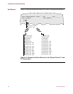
5-8 Channelized Data
Configuring Channelized Data
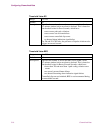
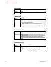
Description: Selects type of zero suppression used on the T1 link.
• B8ZS: Consecutive 8 zero suppression (clear channel)
• B7ZS: Stuffing: (56k x N)
• AMI: Alternate mark inversion (user equipment must
maintain density)
Line Coding Type
(continued)
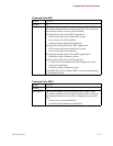
Transmit Clock
Range: INT, REC
Default: INT
Description: Selects the source of transmit clock.
• INT: Internal Oscillator
• REC: Received Timing
N
o
t
e
Only one T1 port on the card can be selected for REC timing.
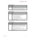
Line Build Out
Range: 0 to 4
Default: 0
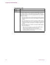
Description: Select the Line Build Out to match the physical interface. For a
DSX interface, select the number based on the cable length:
• 0: 0 to 133 ft
• 1: 134 to 266 ft
• 2: 267 to 399 ft
• 3: 400 to 533 ft
• 4: 534 to 655 ft
For a DS1 interface, select the number based on the signal level:
• 0: 0 dB
•1: -7 dB
•2: -15 dB
•3: -22 dB
• 4: Invalid for DS1 interfaces
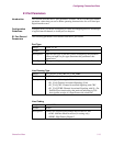
Facility Data Link
Range: None, ANSI, ATT
Default: None
Description: Describes the use of the facility data link channel. Appears only if
ESF is selected as Line Framing Type.


