


5. Connections
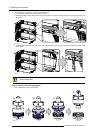
RS232/422 input port RS232/422 output port
Pin Description Pin Description
8
CTS : Clear To Send
8
— (not connected) —
9 RI:RingIndicator 9
— (not connected) —
54321
12345
9876
6789
A B
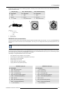
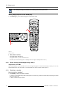
Image 5-13
A Pin numbering male DB–9 connector.
B Pin numbering female DB-9 connector.
RS232
An Electronic Industries Association (EIA) serial digital interface standard specifying the characteristics of the commu-
nication path between two devices using either D-SUB 9 pins or D-SUB 25 pins connectors. This standard is used for
relatively short-range communications and does not specify balanced control lines. RS-232 i
s a serial control standard
with a set number of conductors, data rate, word length and type of connector to be used. The standard specifies com-
ponent connection standards with regard to computer interface. It is also called RS-232-C, which is the third version
of the RS-232 standard, and is functionally identical to the CCITT
V.24 standard. Logical ’0’ is > + 3V, Logical ’1’ is < -
3V. The range between -3V and +3V is the transition zone.
RS422
An EIA serial digital interface standard that specifies the electrical characteristics of balanced (differential) voltage,
digital interface circuits. This standard is usable over longer distances than RS-232. This signal governs the asyn-
chronous transmission of computer data at speeds of up to 920,000 bits per second. It is also used as the serial port
standard for Macintosh computers. When the difference between the 2 lines is < - 0.2V that equals with a logical ’0’.
When the difference is > +0.2V that equals to a logical ’1’..
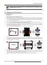
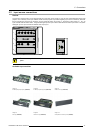
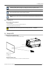
Ethernet network communication
The FLM projector can be connected to a LAN (local area network) using port 1 (F) or port 2 (G) on the communication interface.
Once connected to the LAN, users are capable of accessing the projector from any location, inside or outside (if allowed) their
company network using the FLM control software: Projector Toolset. This toolset locates the projector on the network in case there
is a DHCP server or the user can insert the correct IP-address of the projector to access the projector. Once accessed, it is possible
to check and manipulate all the projector settings. Remote diagnostics, control and monitoring of the projector can then become a
daily and very simple operation. The network connectivity permits to detect potential errors and consequently improve the time to
servicing.
As there is a need to daisy chain projectors when they are in Ethernet network, an Ethernet switch is build in. the incoming network
is hereby available for the internal PC and for the next device in the chain. In this way a ’star’ network interconnection can be avoid.
The switch used is a stand alone 10/100Mbit Ethernet switch. This assures no influence on the network speed. Whenever a slow
(10Mbit) device is connected the speed between the 100Mbit devices remains 100Mbit.
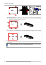
Both Ethernet ports (F & G) are equipped with a yellow and green a LED. The yellow LED lights up in case the port is connected
with a 100Mbit network. The green LED
blinks in case there is network activity.
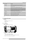
The connectors used for both Ethernet ports (F & G) are of rugged Neutrik EtherCon RJ45 type, which is
compatible with standard RJ45 cable connector. Straight (most common) as well as cross linked network
cables can be used. The 2 ports are functionally identical. Both ports are connected via the projector hub
(Auto sensing enabled).
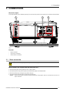
10/100 Base-T — RJ45 port
Pin Description
1TXD+
2TXD-
3RXD+
4
—
5
—
6RXD-
40
R5976986 FLM HD18 15/03/2010