


5. Connections
5.2 Input source connections
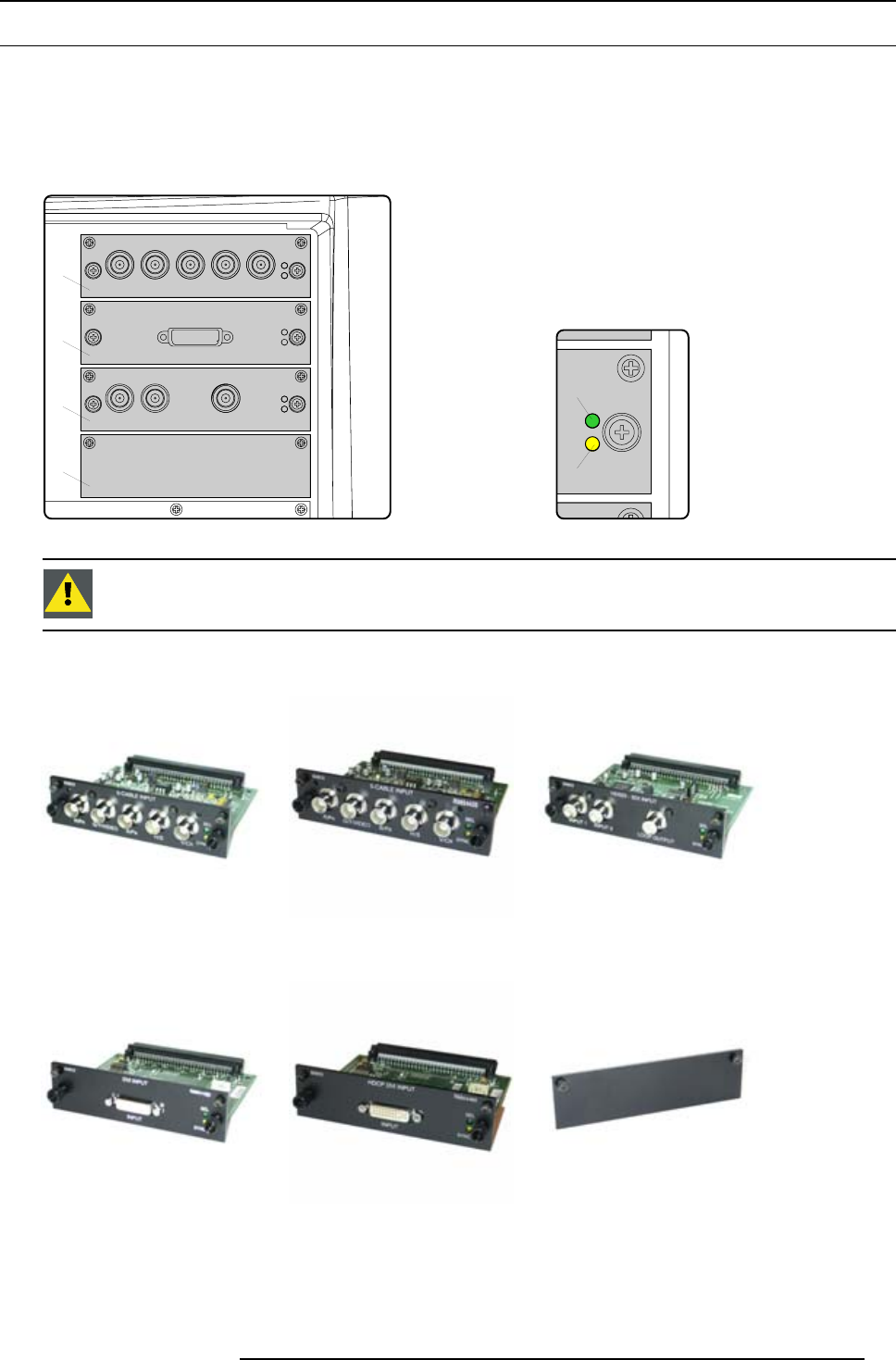
General
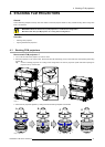
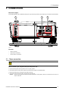
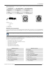
The input and communication unit is equipped with four input slots, which accept any type of input module designed for the FLM
projector. The modularity of the input modules makes the FLM projector very flexible regarding input source connectivity. Note that
the slot numbering is done from top to bottom. So, the uppermost slot is slot number “1”, the second is slot number “2”... etc. All
input modules have two status LED’s. The green LED lights up if the input module is selected as the active input module. The yellow
LED lights up if the input module has detected valid input syncs.
Y
1
2
3
4
G
Image 5-4
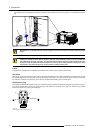
CAUTION: Always install a cover plate on an unused input slot. This to prevent dust intrusion into the pro-
jector.
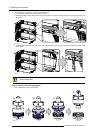
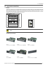
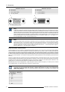
Available input modules
Image 5-5
5 Cable input (Multi purpose) (R9854430).
Image 5-6
5 Cable input(Multi purpose)(R9854435).
Image 5-7
HDSDI - SDI input (R9854450).
Image 5-8
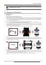
DVI input (R9854460).
Image 5-9
HDCP DVI input (R9854465).
Image 5-10
Cover plate for unused inputslot (R848607).
R5976986 FLM HD18 15/03/2010 37