


5. Connections
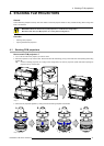
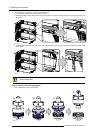
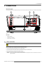
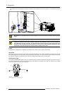
The FLM HD18 is standard equipped with one 5 cable input module, one HDSDI - SDI input module and one
DVI input module. Input slot number 4 (lowermost) is covered with a input cover plate.
For more information about the FLM input modules see chapter “Specifications”.
5.3 Communication connections
Communication interface
1 2
3
2
1
3
PUSH
PC CARD
PORT 1
PORT 2
10/100 BASE-T
USB
OK REC
DIAGNOSTIC CODE IR RECEIVER
STBY / ON
WARNING IR
REMOTE
CTRL IN
REMOTE
CTRL OUT
RS232 / 422 OUT
RS232 / 422 IN
F G H I J K L M N O
EDCBA
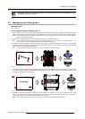
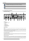
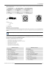
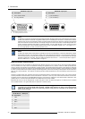
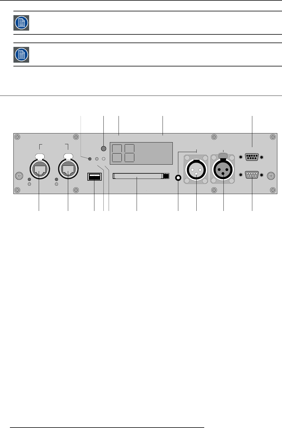
Image 5-11
A Warning LED.
B Projector status LED.
C Two digit LED display for diagnostic code.
D IR-receiver (side).
E RS232/422 loop through output port.
F Ethernet port 1.
G Ethernet port 2.
H USB port.
I IR signal received LED.
J IR signal acknowledged LED.
K PCMCIA card-bus (slot).
L Mini-jack input port for remote control.
M XLR input port for remote control.
N XLR output port for remote control.
O RS232/422 input port.
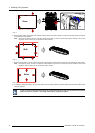
Projector status
The projector “status” LED (B) lights up green while in operation. The same LED lights up red when the projector is switched to
standby.
Besides the projector status LED (B) the communication interface has also a “warning” LED (A) which blinks in case the projector
encounters an internal problem concerning fan speed, temperature, supply voltages, ... etc. These type of problems still allows
the projector to operate (the show can go on) but an action will be required within a short time period. More information about the
involved problem is given on the local LCD display of the projector.
A two character 7-segment display (C) shows, during normal operation, the selected input slot number. If an error has occurred then
an error code appears on this two digit LED display.
IR communication (RC5)
An IR receiver (
D) is mounted on the communication interface. Note that there is also an IR receiver mounted at the front and at the
rear of the projector. When using the remote control unit (wired or wireless), the “IR REC” (I) and the “IR OK” (J) LED’s will light up
indicating an IR signal was received and recognized.
Wired remote control
If desired the remote control unit can be wired and plugged in into the 3,5 mm mini jack socket (L) or, when using a rugged wire
with XLR plugs, plugged in into the male XLR port (M) on the communication interface. Besides the XLR input port a female XLR
connector (N) for wired RC5 output is provided. This connector creates a buffered RC5 signal, available for the next projector in
the daisy chain. Whenever the projector has no power, a passive loop through is created from the remote control input port to the
38
R5976986 FLM HD18 15/03/2010