Section 19 Serial I/O with FIFO
R01UH0134EJ0400 Rev. 4.00 Page 979 of 2108
Sep 24, 2014
SH7262 Group, SH7264 Group
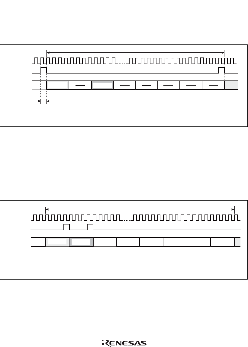
(5) 16-bit Stereo Data (2)
Falling edge sampling, slot No.0 used for left channel data, slot No.2 used for right channel data,
and frame length = 128 bits
SIOFSCK
SIOFRxD
SIOFTxD
SIOFSYNC
TRMD[1:0]=00 or 10,
TDLE=1,
RDLE=1,
REDG=1,
TDLA[3:0]=0000,
RDLA[3:0]=0000,
FL[3:0]=1110 (frame length: 128 bits)
TDRE=1,
RDRE=1,
TDRA[3:0]=0010,
RDRA[3:0]=0010
L-channel
data
Slot No.0 Slot No.1 Slot No.2 Slot No.3 Slot No.4 Slot No.5 Slot No.6 Slot No.7
Specifications:
1 frame
1 bit delay
R-channel
data
Figure 19.14 Transmit and Receive Timing (16-Bit Stereo Data (2))
(6) Synchronization-Pulse Output Mode at End of Each Slot (SYNCAT Bit = 1)
Falling edge sampling, slot No.0 used for left channel data, slot No.1 used for right-channel data,
and frame length = 128 bits
In this mode, valid data must be set to slot No. 0. In addition, make sure that valid data is
transmitted/received or transmitted.
SIOFSCK
SIOFRxD
SIOFTxD
SIOFSYNC
TRMD[1:0]=00 or 10,
TDLE=1,
RDLE=1,
SYNCAT=1
REDG=0,
TDLA[3:0]=0000,
RDLA[3:0]=0000,
FL[3:0]=1110 (frame length: 128 bits),
TDRE=1,
RDRE=1,
TDRA[3:0]=0001,
RDRA[3:0]=0001,
L-channel
data
R-channel
data
Slot No.0 Slot No.1 Slot No.2 Slot No.3 Slot No.4 Slot No.5 Slot No.6 Slot No.7
Specifications:
1 frame
Figure 19.15 Transmit and Receive Timing (16-Bit Stereo Data)


