


7 - 12 7 - 12
MELSOFT
7. SYSTEM CHECKING FROM PERIPHERAL DEVICE
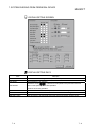
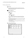
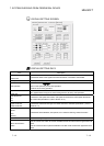
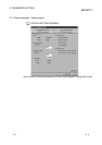
DISPLAY/SETTING SCREE
N
DISPLAY/SETTING DATA
Item Description
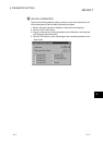
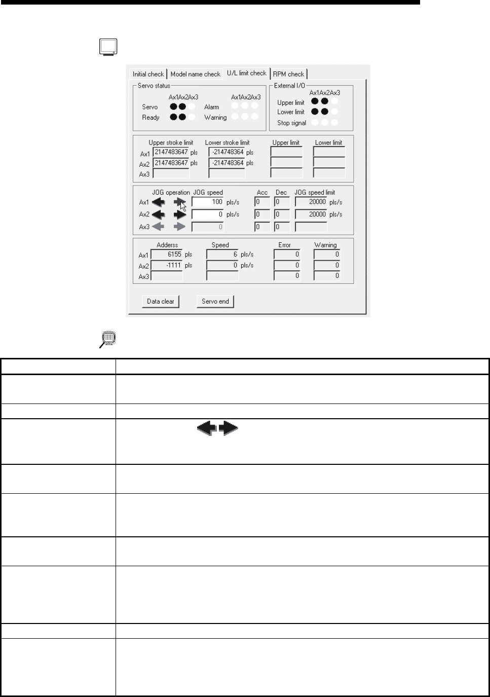
Servo status
External I/O
Indicates the states of the signals from external devices connected to the AD75M.
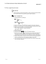
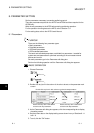
JOG speed Set the speed for JOG operation.
JOG operation
Choose the arrow (
) of the axis for JOG operation and press the mouse's left
button or the space key to start JOG operation.
The arrow is red during operation.
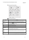
Upper limit
Lower limit
"OK" appears when the upper or lower limit signal turns off during JOG operation.
JOG speed limit
Acc
Dec
Indicates the JOG speed limit values, JOG speed accel times and JOG speed decel times
set to extended parameters 2 (refer to Section 8.1.4).
Upper stroke limit
Lower stroke limit
Indicates the software stroke upper and lower limits set to extended parameters 1 (refer to
Section 8.1.3).
Address
Speed
Error
Warning
Indicates the feed addresses, axis speeds, error codes and warning codes of the axes.
"Data clear" button When rechecking the upper or lower limit, click this button to clear the result.
"Servo end"/"Online"
button
Click the "Servo end" button to end the AD75M test mode and terminate the upper/lower limit
check.
Click the "Online" button to place the AD75M in the test mode and start the upper/lower limit
check.