


11 - 22 11 - 22
MELSOFT
11. POSITIONING DEBUGGING
DISPLAY/SETTING DATA
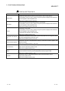
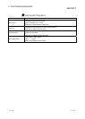
Item Description
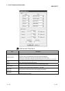
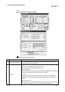
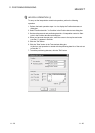
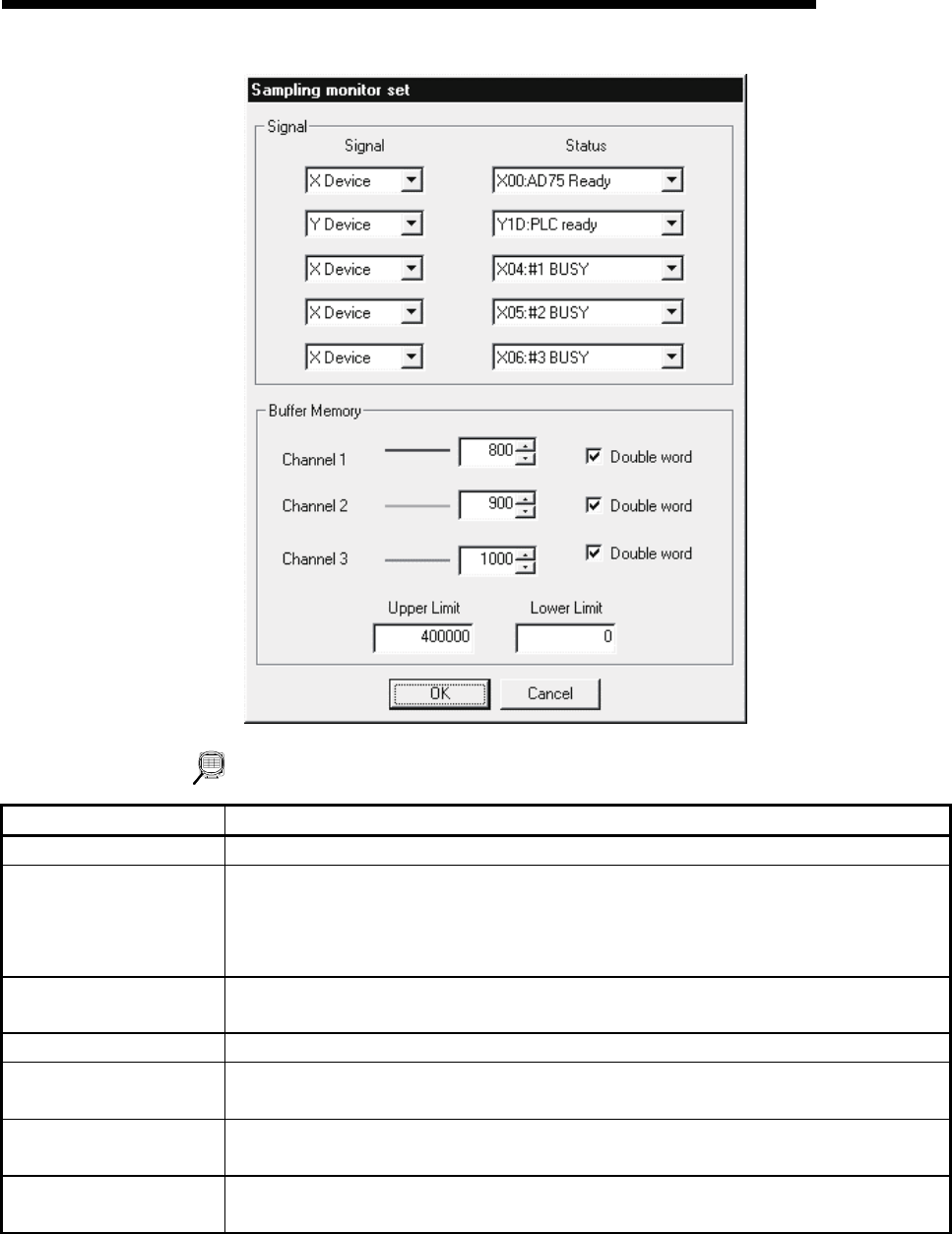
"Data set" button Click this button to display the Sampling monitor set dialog box.
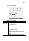
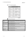
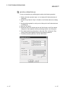
Sampling monitor
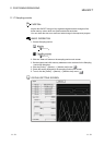
For signals, their ON/OFF states are indicated by HIGH/LOW.
For buffer memory, the addresses and waveform data are displayed.
Waveforms are magnified or reduced according to the main screen size.
The sampling result display changes in 500ms increments and its cycle ends in 2 minutes.
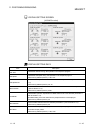
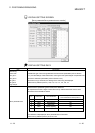
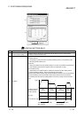
Signal
Choose the types of the sampling-monitored signals from the X device, Y device, external I/O
signal, status signal and servo status signal.
Status Choose the sampling-monitored signals from the selected signal types.
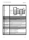
Buffer memory
Set the AD75 buffer memory addresses and sizes (device sizes) to be sampling monitored.
The setting range is buffer memory address No.s 1 to 1099.
Upper Limit
Lower Limit
Set the upper and lower limit values of the sampling result display.
"OK" button
Click this button to close the Sampling monitor set dialog box and display the settings on the
sampling monitor main screen.