6.1.2 Changing the operating state
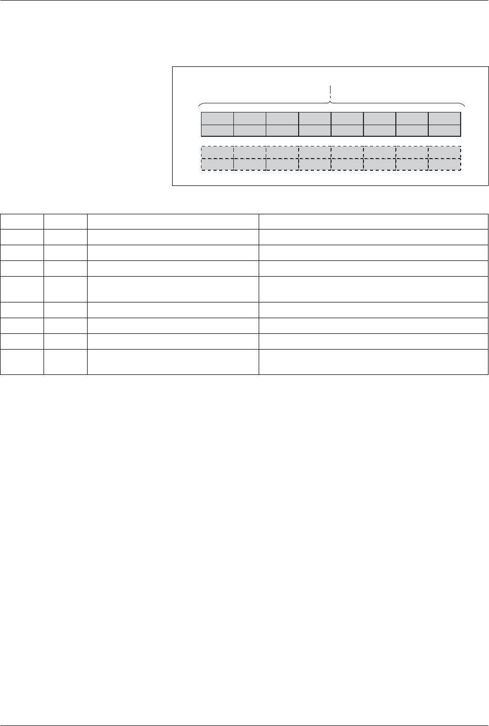
Bits 8 ... 15 of the word "dmControl" are used to set the operating
state.
15
CU
14
CH
13
SH
12
-
11
FR
10
QS
9
EN
8
DS
7
MT
6
ACTION
5
ACTION
4
MODE
3
MODE
2
MODE
1
MODE
0
MODE
dmControl
Figure 8: Structure dmControl bits 8 ... 15
Bit Name Meaning Operating state
8 DS Disable power stage
6 Operation Enabled -> 4 Ready To Switch On
9 EN Enable power stage
4 Ready To Switch On -> 6 Operation Enabled
10 QS Executing a "Quick Stop"
6 Operation Enabled -> 7 Quick Stop Active
11 FR Execute "Fault Reset"
7 Quick Stop Active -> 6 Operation Enabled
9 Fault -> 4 Ready To Switch On
12 - Reserved Reserved
13 SH Execute "Halt"
6 Operation Enabled
14 CH Clear "Halt"
6 Operation Enabled
15 CU Resume operating mode interrupted by
"Halt"
6 Operation Enabled
In the case of an access, the bits respond to a 0->1 change to trigger
the corresponding function.
If a request for changing the operating state is not successful, this
request is ignored. There is no error response.
Ambivalent bit combinations are treated in accordance with the follow-
ing priority list (highest priority bit 8, lowest priority bit 14 and bit 15):
•
Bit 8 (disable power stage) prior to bit 9 (enable power stage)
•
Bit 10 ("Quick Stop") prior to bit 11 ("Fault Reset")
•
Bit 13 (execute "Halt") prior to bit 14 (clear "Halt") and bit 15
(resume operating mode interrupted by "Halt")
LXM32M
6 Operation
Modbus-TCP module
53
0198441113843, V1.01, 01.2012


