


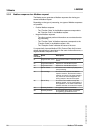
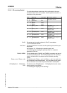
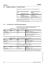

3.3.4.1 I/O scanning Output
The table below shows the structure of the cyclic data for the com-
mands from the master to the product. See the product manual for a
description of the parameters.
Byte Meaning Data type Parameter address
0 ... 7 ParCh - Parameter channel
8 ... 9 dmControl INT -
10 ... 13 RefA32 DINT -
14 ... 17 RefB32 DINT -
18 ... 21 Ramp_v_acc DINT Parameter Ramp_v_acc
Modbus 1556
22 ... 25 Ramp_v_dec DINT Parameter Ramp_v_dec
Modbus 1558
26 ... 29 EthOptMapOut1 DINT Parameter EthOptMapOut1
Modbus 17500
30 ... 33 EthOptMapOut2 DINT Parameter EthOptMapOut2
Modbus 17502
34 ... 37 EthOptMapOut3 DINT Parameter EthOptMapOut3
Modbus 17504
ParCh Parameters can be read or written via "ParCh", see chapter
"3.3.4.3 Parameter channel".
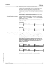
dmControl The word "dmControl" is used to set the operating state and the oper-
ating mode.
See chapters "6.1.2 Changing the operating state" and
"6.2.2 Starting and changing an operating mode" for a detailed
description of the bits.
RefA32, RefB32 The two double words "RefA32" and "RefB32" are used to set two val-
ues for the operating mode. The meaning depends on the operating
mode; it is described in the chapters on the individual operating
modes.
Ramp_v_acc / Ramp_v_dec The double words "Ramp_v_acc" and "Ramp_v_dec" are used to set
the acceleration and the deceleration. They correspond to the param-
eters of the same name. See the product manual for a description.
EthOptMapOut1 ... EthOptMap-
Out3
The double words EthOptMapOut1 ... EthOptMapOut3 contain select-
able parameters, see chapter
"5.7.3 Setting the mapping for I/O scanning".
LXM32M
3 Basics
Modbus-TCP module 23
0198441113843, V1.01, 01.2012