


6 • Configuring FR and ATM features Model 3096RC G.SHDSL T-DAC Administrators’ Reference Guide
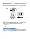
70 Frame Relay Service Interworking (FRF.8)
DE Mapping
The DE Mapping variable is used to determine how the Frame Relay DE field (Discard Eligi-bility) will be
mapped to the ATM CLPI (Cell Loss Priority Indication) and vise versa. The following options are available:
• Always_zero:
- Frame Relay: All Frame Relay packets will have the DE field in the header set to a constant value of 0.
- ATM: All ATM cells will have the CLPI field set to a constant value of 0.
• Always_one:
- Frame Relay: All Frame Relay packets will have the DE field in the header set to a constant value of 1.
- ATM: All ATM cells will have the CLPI field set to a constant value of 1.
• Convert:
- Frame Relay to ATM Direction: The system will convert the DE field received from the Frame Relay
packet into the CLPI field of the outgoing ATM cell.
- ATM to Frame Relay Direction: The system will convert the CLPI bit received from the ATM cells into
the DE field of the outgoing Frame Relay packet.
FECN Mapping
The FECN Mapping variable is used to determine how the Frame Relay FECN (Forward Explicit Congestion
Notification) bit will be mapped to the ATM EFCI (Explicit Forward Congestion Indica-tion) bit and vise
versa. The following options are available:
• Always_zero:
- Frame Relay: All Frame Relay packets will have the FECN bit in the header set to a constant value of 0.
- ATM: All ATM cells will have the EFCI bit set to a constant value of 0.
• Always_one:
- Frame Relay: All Frame Relay packets will have the FECN bit in the header set to a constant value of 1.
- ATM: All ATM cells will have the EFCI bit set to a constant value of 1.
• Convert:
- Frame Relay to ATM Direction: The system will convert the FECN bit received from the Frame Relay
packet into the EFCI bit of the outgoing ATM cell.
- ATM to Frame Relay Direction: The system will convert the EFCI bit received from the ATM cells into
the FECN bit of the outgoing Frame Relay packet.
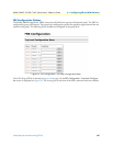
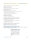
FRS Name
Allows the user to name the FRS channel. This is helpful when viewing multiple connections to determine
which DLCI/VPI/VCI combination is associated with each channel.
• FRS state: The state variable allows the user to enable or disable the channel for operation.
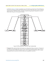
The Frame Relay Service Interworking functions on the Patton Electronics Model 3086FR are also defined
as sixty-four channels. Each channel creates a connection between a single DLCI on the Frame Relay net
-