


6 • Configuring FR and ATM features Model 3096RC G.SHDSL T-DAC Administrators’ Reference Guide
56 Introduction
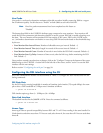
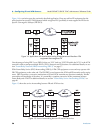
Figure 14 is a variation upon the previously described application. Here one end has FR equipment but the
other location has special ATM equipment which recognizes FR. Specifically it must support the FR Service
Specific Convergence Sublayer (FR-SSCS).
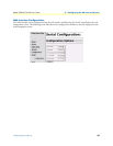
Figure 14. Application with one location having FR equipment and the other ATM
equipment
that recognizes FR
One advantage of using FRF.5 over FRF.8 is that one VCC (and one VCI/VPI within the VCC) in the ATM
network is used to transport multiple DLCIs (PVCs) between two FR locations. For additional details, see sec
-
tion “Frame Relay Network (FRN) Interworking (FRF.5)” on page 57.
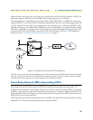
With Frame Relay Service (FRS) Interworking (FRF.8), ATM CPE equipment on one end may operate with
FR CPE equipment on the other end. The FRS IWF occurs between the ATM and FR networks and/or equip
-
ment. FRF.8 provides a conversion mechanism so FR and ATM networks may function seamlessly. Neither
network has no knowledge of the other. It is essentially a complete conversion of the parameters between
Frame Relay and ATM. For additional details, see section
“Frame Relay Service Interworking (FRF.8)” on
page 66.
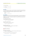
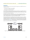
Figure 15 shows the service interworking between FR and ATM services.
Figure 15.
Service interworking between FR and ATM services