


6 • Configuring FR and ATM features Model 3096RC G.SHDSL T-DAC Administrators’ Reference Guide
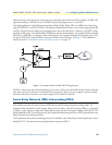
62 Frame Relay Network (FRN) Interworking (FRF.5)
- Convert: The system will convert the DE field received from the Frame Relay packet into the CLPI field
of the outgoing ATM cell that is generated by the segmentation process.
• CLPI Mapping: The CLPI Mapping variable is used to determine how the ATM CLPI (Cell Loss Priority
Indication) bit in the ATM cell will be mapped to the DE (Discard Eligibility) bit of the resulting Frame
Relay packet. There are two options available.
- Fr_sscs_only: The FR-SSCS removed from the ATM header PDU is used to set the DE bit in the out-put
Frame Relay packet. The CLPI bit from the ATM cell is ignored.
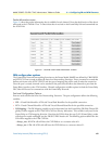
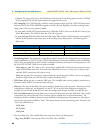
- Fr_sscs_and_clpi: Both the DE bit from the ATM header PDU and the CLPI bit from the received ATM
cells are used to determine the output state of the resulting Frame Relay packet. The following table
defines how.
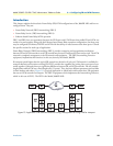
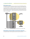
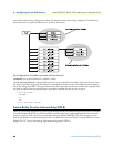
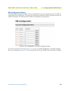
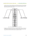
• Multiplexing Mode: The MuxMode variable allows multiple channels to be multiplexed onto a single port.
A port is defined by its’ VPI/VCI of the ATM rfc1483 data path. Channels are defined by their Frame Relay
DLCI. Thus, the multiplexing mode will allow multiple Frame Relay channels to be transported over a sin-
gle ATM VPI/VCI link. There are two options available.
– Mux_many_to_one: The “many to one” option allows multiple DLCI channels to be transported over a
single ATM rfc1483 connection. Note that if the MuxMode is not set to “many to one” trying to add
multiple DLCI connections will result in errors.
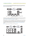
– Mux_one_to_one: The “one to one” option notifies the system that there will be a one to one mapping
between a single ATM port VPI/VCI and a single Frame Relay DLCI.
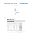
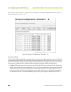
• FRN Name: Allows the user to name the FRN port. This is helpful when viewing multiple connections to
determine which VPI/VCI is associated with each port.
• FRS state: The state variable allows the user to enable or disable the port for operation. Note that port level
configuration variables are not changeable “on the fly”. If it is required that configuration changes are
required, the user should disable the port, make the configuration changes, and then re-enable the port.
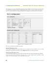
• Port Level Maintenance: Port level maintenance creates an LMI session across the ATM link. This is useful
to determine the status of the link. There are three options available for Port Level Maintenance. The
description of these variables is identical to that described in the beginning of this document. Note that in
each case the only option available is “both”. This means that the system is performing both “Network” and
“User” side LMI functions.
– 933A_both
– 617D_both
– LMI_both
• Port Level Mgt State: This variable defines the state of the Port Level Maintenance.
- Mgt_Port_DOWN: Currently the LMI on the DTE side is DOWN
CLPI received from ATM cell DE from FR-SSCS of ATM cell Outgoing DE bit of FR Packet
0 0 0
1 X 1
X 1 1