


Status LEDs 136
Model 3086FR ATM IAD User Guide 12 • Monitoring Status
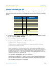
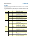
Status LEDs
The LEDs indicate the status of the Power, the WAN (DSL) inter-modem link, Sync Serial or T1/E1 port, the
Ethernet connection, and Status.
All LED indicators will present the same looking profile (e.g., clear) when unlit due to being single color, water
clear, high efficiency LEDs.
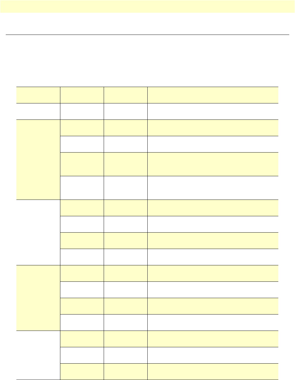
Table 5. Status LED descriptions
Power Green ON indicates that power is applied. Off indi-
cates that no power is applied.
WAN (DSL) Link Green Solid green: connected
Off: disconnected
Sync Serial TD Green Green: indicates a binary ‘0’ condition
off: indicates a binary ‘1’or idle condition
RD Green Green: indicates a binary ‘0’condition
off: indicates a binary ‘1’ or idle condition
CTS Green ON: indicates the CTS signal from the Frame
Relay to ATM Converter is active, binary ‘1’
off: indicates CTS is binary ‘0’
DTR Green ON: indicates the DTR signal from the DTE
device attached to the serial port is active,
binary ‘1’
T1/E1 Link Green On: indicates the T1/E1 interface is connected to a
live T1/E1 line
LOS Red On: indicates the T1/E1 interface is not connected
to an active T1/E1 line
TD Green Green: indicates a binary ‘0’ condition
off: indicates a binary ‘1’or idle condition
RD Green Green: indicates a binary ‘0’condition
off: indicates a binary ‘1’ or idle condition
Ethernet Link Green ON: indicates an active 10/100 BaseT connec-
tion
100M Green ON: connected to a 100BaseT LAN
Off: connected to a 10BaseT LAN
Tx Green Flashing: when transmitting data from the Frame
Relay to ATM Converter to the Ethernet
Rx Green Flashing: when transmitting data from the Ether-
net to the IAD.
Status NS Red ON: incidates absence of a valid DSL connec-
tion
ER Red flashes once: indicates bit errors occurring dur-
ing 511/511E tests
TM Yellow ON: is under one of the test modes (local loop,
remote loop, or V.54 BER pattern)