


Index
IN-4
Cisco AS5350 and Cisco AS5400 Universal Gateway Card Installation Guide
78-13311-01
removing a carrier card 2-3
removing the carrier card from the Cisco AS5350
(figure)
2-4
removing the carrier card from the Cisco AS5400
(figure)
2-4
removing the T1 or E1 DFC 3-3
removing the universal port DFC 5-2
required tools and equipment 1-3
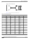
RJ-45 to Bare Wire Interface Cable (figure) A-2
RJ-45 to BNC Interface Cable for 75-Ohm, Unbalanced
Connections (figure)
A-2
RJ-45 to RJ-45 Interface Cable (figure) A-2
RJ-45 to Twinax Interface Cable for 120-Ohm, Balanced
Connections (figure)
A-2
routing cables with molded RJ-45 ends of cables flush with
bracket edges (figure)
A-7
routing cables with molded RJ-45 ends of cables next to
each other (figure)
A-6
RX MON Bantam Jack 6-9
S
safety, ground connections 1-2
safety with electricity 1-2
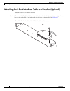
securing the cable bracket to the rack (figure) A-8
service and support 2-7, 3-14, 4-7, 5-9, 6-10
Slot Numbering on the Cisco AS5350 Chassis
(figure)
3-3, 4-2, 5-2, 6-6
Slot Numbering on the Cisco AS5400 Chassis
(figure)
3-4, 4-3, 5-3, 6-6
SPE Firmware 5-9
support, getting technical 2-7, 3-14, 4-7, 5-9, 6-10
Symbols
Caution
viii
Note viii
Timesaver viii
Tips ix
Warning ix
T
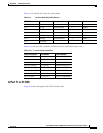
T1 and E1 Cable and Port Pinouts A-1
T1 and E1 Cable Assemblies (table) A-2
T1 network specifications (table) 3-2
T1 or E1 DFC, overview 3-1
T1 or E1 DFCs (table) 6-3
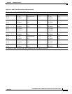
T1 or E1 Port Pinouts (table) A-1
T3 cable pinouts A-10
T3 DFC, installation and removal 4-2
T3 DFC, overview 4-1
T3 DFC LEDs (figure) 6-2
T3 Dial Feature Card (figure) 4-1
Tables
8 PRI T1/E1 DFC Interface Cable
A-3
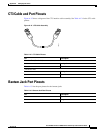
Bantam Jack Port Pinouts A-10
CT3 Cable Pinouts A-10
Document Organization vii
E1 Network Specifications 3-2
LEDs 6-3
T1 and E1 Cable Assemblies A-2
T1 Network Specifications 3-2
T1 or E1 DFC LEDs 6-3
T1 or E1 Port Pinouts A-1
T3 DFC LEDs 6-4
Universal Port LEDs 6-5
technical assistance, getting xii
technical support 2-7, 3-14, 4-7, 5-9, 6-10
telecommunications lines warning 3-9
testing, using the Bantam Jack ports 6-9
Tighten the Captive Screws on the Cisco AS5350
(figure)
2-6, 3-10, 4-6, 5-8
Tighten the Captive Screws on the Cisco AS5400
(figure)
2-6, 3-10, 4-7, 5-8
timesaver symbol, meaning of viii
tips symbol, meaning of ix
tools required 1-3
troubleshooting 6-1
troubleshooting, environment 6-6