


Index
IN-3
Cisco AS5350 and Cisco AS5400 Universal Gateway Card Installation Guide
78-13311-01
installing the T1 or E1 DFC 3-9
installing the T3 DFC 4-5
installing the universal port DFC 5-7
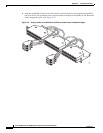
install the carrier card in the Cisco As5350 (figure) 2-5
install the carrier card in the Cisco AS5400 (figure) 2-5
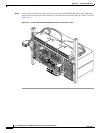
Install the DFC in the Cisco AS5400 (figure) 5-7
Install the T1 or E1 DFC in the Cisco AS5350
(figure)
3-9
Install the T1 or E1 DFC in the Cisco AS5400
(figure)
3-10
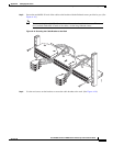
Install the T3 DFC in the Cisco AS5350 (figure) 4-6
Install the T3 DFC in the Cisco AS5400 (figure) 4-6
Install the Universal Port DFC in the Cisco AS5350
(figure)
5-7
J
J-45 to DB-15 Interface Cable (figure) A-2
jewelry removal warning 1-2
L
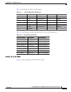
LEDs (table) 6-3
LEDs, location and description on DFCs 6-1
LEDs, T1 or E1 DFC (table) 6-3
LEDs, T3 DFC (table) 6-4
LEDs, universal port DFC (table) 6-5
lightning activity warning 2-3, 3-4, 3-9, 4-3, 4-5, 5-3, 5-7
Loosen the Captive Screws on the Cisco AS5350
(figure)
2-3, 3-5, 4-4, 5-4
Loosen the Captive Screws on the Cisco AS5400
(figure)
2-4, 3-5, 4-4, 5-4
M
mixing WAN DFCs, troubleshooting 6-5
monitoring mode for the T1, E1, and T3 DFCs 6-9
N
network interfaces, troubleshooting 6-10
new hardware features xiii
note symbol, meaning of viii
O
obtaining documentation xi
online insertion and removal (OIR) of DFCs 2-2
online insertion and removal (OIR) of the T1 or E1
DFC
3-3
online insertion and removal (OIR) of the universal port
DFC
5-2
online installation and removal (OIR) of the T3 DFC 4-2
operating temperature 6-6
organization, document vii
overview, Dial Feature Cards 2-1
overview, T1 or E1 DFC 3-1
overview, T3 DFC 4-1
overview, universal port DFC 5-1
P
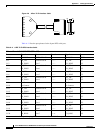
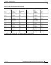
Pinouts
8 PRI T1/E1 DFC interface cable
A-3
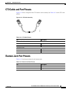
Bantam Jack port A-10
CT3 Cable Pinouts A-10
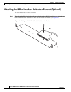
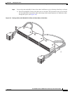
placing the molded RJ-45 end of the cable on the bracket
(figure)
A-5
power supply disconnection warning 2-2
product disposal warning 1-1
R
related documents xiii
Remove the DFC from the Cisco AS5350 4-5
Remove the DFC from the Cisco AS5350 (figure) 3-6, 5-4
Remove the DFC from the Cisco AS5400 (figure) 3-6,
4-5, 5-5