


CHAPTER
2-1
Cisco AS5350 and Cisco AS5400 Universal Gateway Card Installation Guide
78-13311-01
2
Dial Feature Card and Carrier Card Guidelines
This chapter includes the following sections:
• Overview, page 2-1
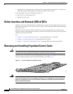
• Online Insertion and Removal (OIR) of DFCs, page 2-2
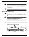
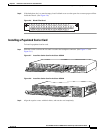
• Removing and Installing Populated Carrier Cards, page 2-2
• Getting Help, page 2-7
• Where to Go Next, page 2-7
Overview
Cisco AS5350 Chassis
The Cisco AS5350 universal gateway chassis has a motherboard, high-speed backplane, and two
backplane slots. One backplane slot accepts one dial feature card (DFC) carrier card and the other
backplane slot accepts one DFC.
Cisco AS5400 Chassis
The Cisco AS5400 universal gateway chassis has a motherboard, high-speed backplane, and four
backplane slots. Three backplane slots accept DFC carrier cards and the other backplane slot accepts one
DFC.
Dial Feature Cards
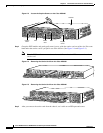
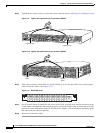
Each DFC carrier card accepts two DFCs which allow online insertion and removal (OIR). (See
Figure 2-1.)
Each DFC is a 5.1 x 13 inch PCI based interface board. The following is a brief description of the trunk
types supported:
• North American robbed-bit signaling (RBS) is supported on T1 trunks, including a variety of North
American RBS protocol, framing, and encoding types on these trunks.
• CAS is supported for E1 trunks, with R2 signaling.
• Many countries require an E1 R2 variant. Per-country defaults are provided for supervisory and
inter-register signaling.
• The CT3 DFC provides physical line termination for a channelized T3 ingress trunk line, and it uses
an onboard multiplexer to multiplex 28 channelized T1 lines into a single channelized T3 line.