


IN-1
Cisco AS5350 and Cisco AS5400 Universal Gateway Card Installation Guide
78-13311-01
INDEX
Numerics
2-Port or 4-Port T1 or E1 DFC LEDs (figure) 6-1
2-Port T1 or E1 DFC (figure) 3-1
4-Port T1 or E1 DFC (figure) 3-2
8-Port T1/E1 Interface Cable (figure) A-3
8-Port T1 or E1 DFC (figure) 3-2
8-Port T1 or E1 DFC LEDs (figure) 6-2
8 PRI T1/E1 interface cable pinouts (table) A-3
A
AC circuit breaker (15A) warning 1-3
attaching the 8-port interface cable bracket A-5
B
Bantam Jack, RX monitor port 6-9
Bantam Jack, TX monitor port 6-9
Bantam Jack port pinouts A-10
bantam jack port pinouts (table) A-10
Bantam Jack ports, testing with 6-9
Bantam Ports (figure) 6-9
blank DFC cover 5-5
blank DFC cover (figure) 2-5, 3-6, 4-5
bracket, 8-port interface cable A-5
C
Cables
8-port interface cable bracket
A-5
8-Port T1/E1 Interface Cable A-3
Connecting the 36-Pin Cable Connector to an 8-port T1
DFC
A-9
J-45 to DB-15 Interface Cable A-2
RJ-45 to Bare Wire Interface Cable A-2
RJ-45 to BNC Interface Cable for 75-Ohm, Unbalanced
Connections
A-2
RJ-45 to RJ-45 Interface Cable A-2
RJ-45 to Twinax Interface Cable for 120-Ohm, Balanced
Connections
A-2
cabling specifications A-1
carrier card, installing 2-5
carrier card, removing 2-3
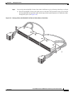
Carrier Card With Two 8 PRI CT1/CE1 Cards
(figure)
2-2
caution symbol, meaning of viii
chassis warning - disconnecting telephone-network
cables
2-3
Configuring Input Impedance for the E1 DFC 3-11
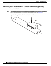
Connecting the 36-Pin Cable Connector to an 8-port T1
DFC
A-9
CT3, drop and insert mode 6-9
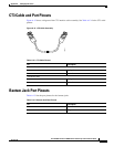
CT3 cable and port pinouts A-10
CT3 cable assembly (figure) A-10
customer equipment warning 3-9
D
DC power disconnection warning 2-3
DFC, online insertion and removal 2-2
Dial Feature Cards, overview 2-1
documentation, getting xi
document organization vii
document organization (table) vii
documents, related xiii
drop and insert mode for the CT3 DFC 6-9