


A-2
Cisco AS5350 and Cisco AS5400 Universal Gateway Card Installation Guide
78-13311-01
Appendix A Cabling Specifications
T1 and E1 Cable and Port Pinouts
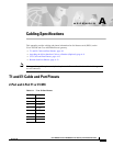
Figure A-1 through Figure A-5 show the types of cables that can connect to the RJ-45 connector on the
T1 or E1 feature card.
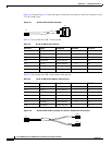
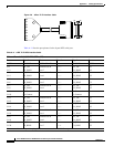
Figure A-1 RJ-45-to-DB-15 Cable Assembly
Table A-2 lists the RJ-45-to-DB-15 cable pinouts.
Table A-3 lists the RJ-45-to-DB-15 null modem cable pinouts.
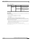
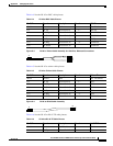
Figure A-2 RJ-45-to-BNC Cable Assembly for 75-Ohm, Unbalanced Connections
35644
J1
J2
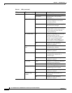
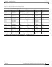
Table A-2 RJ-45-to-DB-15 Cable Pinouts
RJ-45 Pin Signal Description Direction DB-15 Pin
Shield Ground Shell/Braid Shell
J1-1 RX Tip Twisted Pair #1 <— J2-3
J1-2 RX Ring Twisted Pair #1 <— J2-11
J1-3 RX Shield Twisted Pair #3 J2-4
J1-4 TX Tip Twisted Pair #2 —> J2-1
J1-5 TX Ring Twisted Pair #2 —> J2-9
J1-6 TX Shield Twisted Pair #4 J2-2
Table A-3 RJ-45-to-DB-15 Null Modem Cable Pinouts
RJ-45 Pin Signal Description Direction DB-15 Pin
Shield Ground Shell/Braid Shell
J1-1 RX Tip Twisted Pair #1 <— J2-1
J1-2 RX Ring Twisted Pair #1 <— J2-9
J1-3 RX Shield Twisted Pair #3 J2-2
J1-4 TX Tip Twisted Pair #2 —> J2-3
J1-5 TX Ring Twisted Pair #2 —> J2-11
J1-6 TX Shield Twisted Pair #4 J2-4
35643
J1
RX
TX