


A-13
Cisco AS5350 and Cisco AS5400 Universal Gateway Card Installation Guide
78-13311-01
Appendix A Cabling Specifications
CT3 Cable and Port Pinouts
CT3 Cable and Port Pinouts
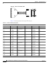
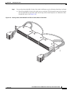
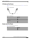
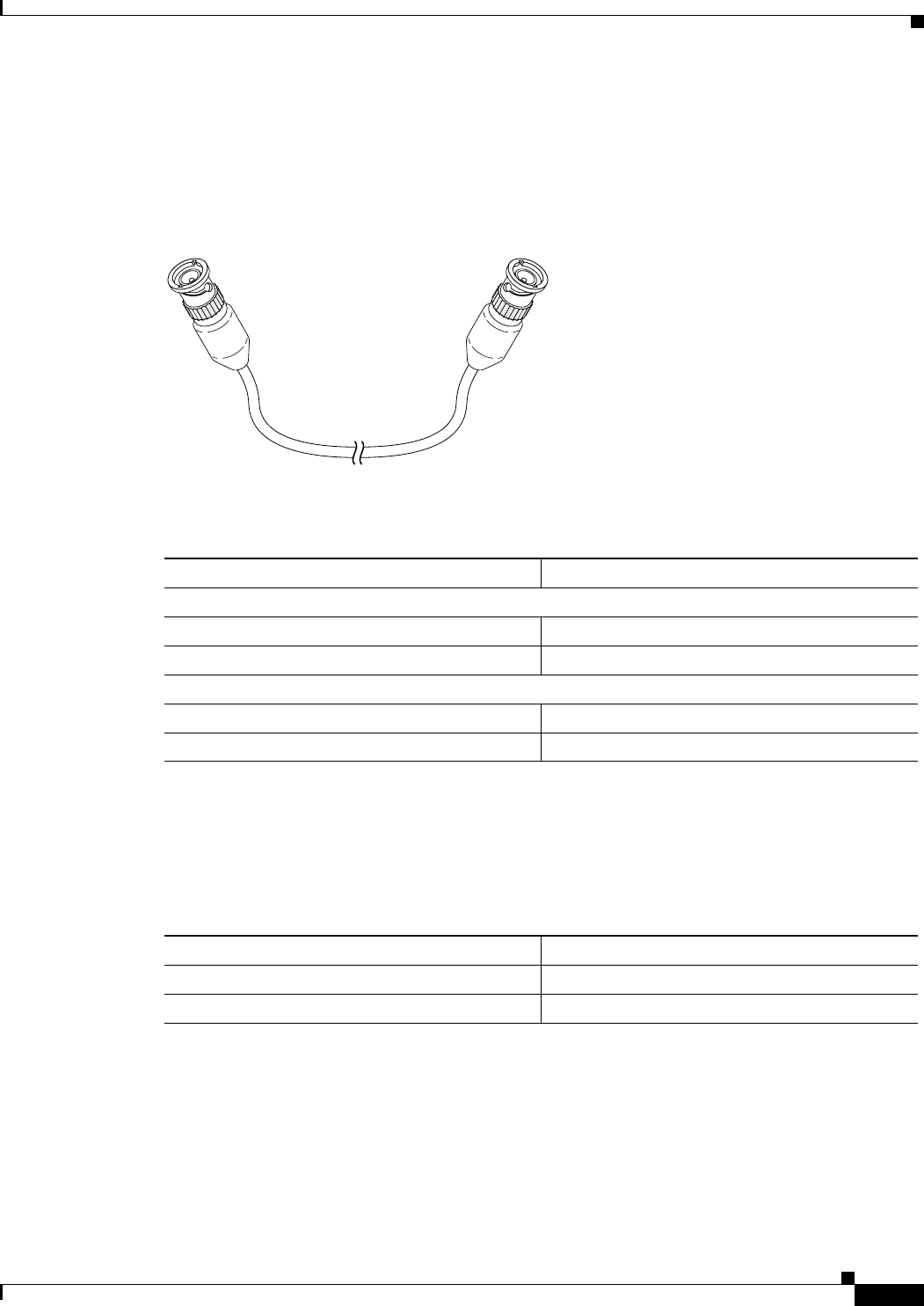
Figure A-12 shows a diagram of the CT3 interface cable assembly. See Table A-12 for the CT3 cable
pinouts.
Figure A-12 CT3 Cable Assembly
Bantam Jack Port Pinouts
Table A-13 lists the port pinouts for the bantam jacks.
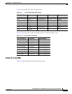
Table A-12 CT3 Cable Pinouts
Pin Description
Receiver Port (On the left)
1Rx signal
2 Ground
Transmitter Port
1 Tx signal
2 Ground
12951
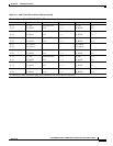
Table A-13 Bantam Jack Port Pinouts
Pin Description
1Tip
2Ring