


3-9
Cisco AS5350 and Cisco AS5400 Universal Gateway Card Installation Guide
78-13311-01
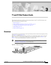
Chapter 3 T1 and E1 Dial Feature Cards
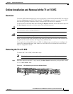
Online Installation and Removal of the T1 or E1 DFC
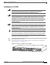
Installing the T1 or E1 DFC
Warning
Do not work on the system or connect or disconnect cables during periods of lightning activity. To
see translations of the warnings that appear in this publication, refer to the Regulatory
Compliance and Safety Information document that accompanied this device.
Warning
The E1 interface card may only be installed in an ACA-permitted customer equipment or a Data
Terminal Equipment (DTE) that is exempted from ACA's permit requirements. The customer
equipment must only be housed in a cabinet that has screw-down lids to stop user access to
overvoltages on the customer equipment. The customer equipment has circuitry that may have
telecommunications network voltages on them. To see translations of the warnings that appear in
this publication, refer to the Regulatory Compliance and Safety Information document that
accompanied this device.
Warning
The telecommunications lines must be disconnected 1) before unplugging the main power
connector and/or 2) while the housing is open. To see translations of the warnings that appear in
this publication, refer to the Regulatory Compliance and Safety Information document that
accompanied this device.
Note When you replace a DFC with a new DFC of the same type in the same slot, the system software will
recognize the new trunk interfaces and bring them up automatically. If you replace the existing DFC
with a new DFC of a different type, you will have to reconfigure the system. For configuration details,
refer to the Cisco AS5350 and Cisco AS5400 Universal Gateway Software Configuration Guide.
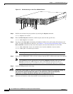
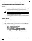
To install the T1 or E1 DFC, follow these steps:
Step 1 Attach an ESD preventive wrist strap.
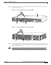
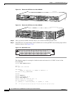
Step 2 Slide the DFC into the slot until the connector pins make contact with the carrier card backplane
connector. (See Figure 3-11 and Figure 3-12.)
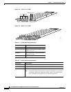
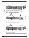
Figure 3-11 Install the T1 or E1 DFC in the Cisco AS5350
36816
0
R
x
ACT
2
P
R
I
OK
T
x
1